 Figure
1. Geometry and display of an MSI image.
Figure
1. Geometry and display of an MSI image.18 October 1995
From: Scott L. Murchie and S.E. Hawkins, III
Subject: Locations of Instrument Footprints in the MSI Field of View
References:
[1] Sadilek, A.C., "Boresight coalignment data for the NEAR spacecraft instruments", APL memorandum S3G-95-115, 21 September 1995
[2] Hawkins, S.E., III, "Image orientation and display from the NEAR MSI", APL memorandum S1I-94-168, 23 September 1994
[3] Peacock, K., "Preliminary calibration of the NIS spectrograph", APL memorandum S1I-95-064, 13 June 1995
[4] Elko, M. and D. Prendergast, "NEAR MSI vibration test alignment analysis", APL memorandum FIF(2)95-U-175, 16 October 1995
From the recent determination of the alignments of MSI, NIS, and NLR [1], we have worked out locations of the instruments' fields-of-view in the MSI frame, in MSI pixel coordinates as displayed on a video monitor. This information is useful in planning of multi-instrument data acquisition sequences at Eros, and in verifying coalignments inflight.
Background
Several aspects of the instruments and their overlap with the MSI frame require consideration in understanding how other instruments' fields-of-view map into the coordinates of MSI pixels.
MSI: The imager field-of-view is 2.9° parallel to the z axis of the spacecraft, and 2.25° parallel to the y' axis, broken down into 537x244 pixels. The center of the field-of-view is designed to be coaligned with the x' axis. Each pixel is rectangular with a 5:3 aspect ratio (approximately 27 µ rad x 16 µ rad, or 0.009225° x 0.005443° ) with the long axis of the pixel perpendicular to the long axis of the image (i.e., parallel to the y' axis). This can be shown for conceptual purposes in Figure 1 at left, as the field-of-view of MSI would appear to an observer on the NEAR spacecraft looking down the x' axis, with the +z axis above:
Figure
1. Geometry and display of an MSI image.
This geometry is significantly distorted by display onto a screen using typical image display software. Many image display programs place the origin of an image in the upper left-hand corner. This is the convention we use here. From the order in which MSI pixels are read out of the instrument, this has the effect of rotating the image 90° clockwise [2]. Furthermore the rectangular pixels are projected onto square raster elements, so that the overall image shape is distorted on the screen. The net effect, shown at right in Figure 1, is that the image is foreshortened and rotated 90° clockwise, 244 rows high and 537 columns wide. Geometric rectification of the image is required to reproduce the scene acquired by the imager.
NIS: This instrument contains a movable scan mirror than scans 140° in the x'-z plane in 0.40° steps. Position 0 is at +30° in the z direction (looks slightly sunward in flight); position 350 is at -110° (looks more-or-less anti-sunward in flight). Position 75 is "nadir," ideally looking down the x' axis, at the spot formed by the transmitted NLR beam and at the center of the MSI field-of-view. Several NIS scan steps are expected to fall within the MSI field of view, those on either side of position 75.
NIS also contains two apertures or "slits." The narrow slit is 0.38° x 0.76° , with the long dimension parallel to the y' axis; the wide slit is square at 0.76° x 0.76° . The center of both is nominally the same. The mirror stepping is across the narrow dimension of the narrow slit, and step size is approximately the same angular distance as the width of the narrow slit.
NLR: The laser rangefinder contains two boresights, one for the transmitter and one for the receiver, both designed to be coaligned with the x' axis. In flight, the alignment of the transmitter relative to MSI is of immediate significance, because the location of the illuminated spot in the imager field-of-view determines what part of the MSI scene is measured by NLR.
Superimposition of the Instrument Fields-of-View
From the measured alignments of the instruments relative to each other and the x' axis [1], and with the above information on the geometries of MSI images and NIS fields-of-view and scan patterns, it is straightforward to derive the locations of NLR and NIS footprints taken simultaneously with an MSI image, in MSI pixel coordinates as displayed on a video monitor.
This is shown in Figure 2 for the narrow NIS slit. (Note: Copies of this memo may be in black-and-white; color versions of this and Figure 3 are available from me.) Locations of the x' axis, NIS and NLR footprints are given in MSI pixel coordinates, with the convention of image origin in the upper left. The two axes (rows and columns on a monitor) are distorted for geometric rectification of the image, to show the correct aspect ratio of the NIS footprints. Uncertainty is on the order of 1 MSI pixel. At the "nadir" position of NIS (mirror position 75), the spacecraft x' axis, the spot formed by the NLR transmitted beam, and the center of the MSI frame all fall within the NIS field-of-view. The footprints for 7 NIS mirror positions (72-78) all fall entirely or almost entirely within the MSI field-of-view; the footprint for position 79 straddles the boundary of the MSI frame in the -z direction.
Figure 3 shows the same, except with the wide slit for NIS. Now, the footprints for mirror positions 73-78 fall entirely or almost entirely in the MSI field-of-view. At mirror position 72, approximately 3/4 of the footprint is in the MSI field-of-view. At mirror positions 71 and 79, half or less of the NIS footprint falls within the MSI field-of-view.
The positions of the x' axis, NLR transmitted spot, and the 4 corners of each NIS slit in different mirror positions are tabulated in Table 1. (Row pixel coordinates in the range 0.0-244.0 and column pixel coordinates in the range 0.0-537.0 are within the MSI field-of-view.)
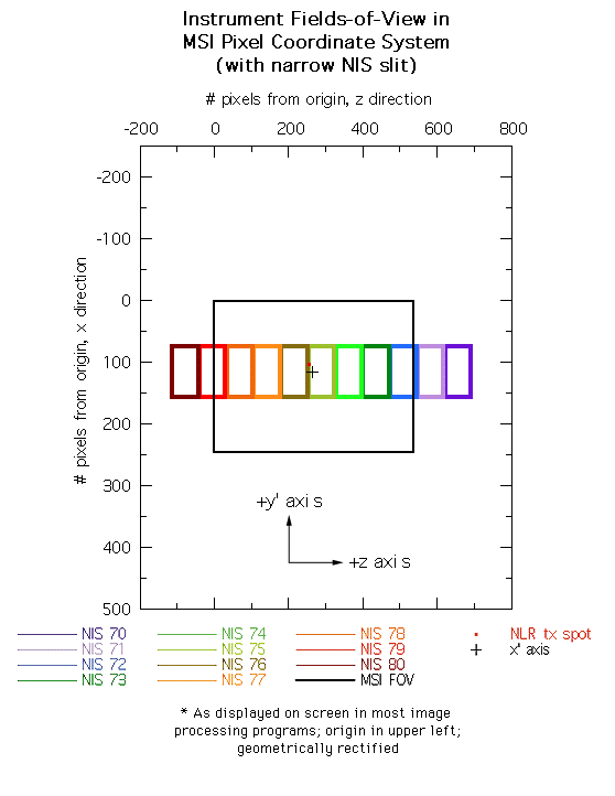
Figure 2. x' axis, the spot formed by the NLR transmitter, and the NIS field-of-view through the narrow slit for different mirror positions shown in MSI pixel coordinates.
Implications for Multi-Instrument Data Acquisition Sequences
Planning to date of data acquisition sequences and inflight calibrations by the NEAR science team has envisioned overlapping coverage by MSI and NIS; future planning for overlapping coverage of either instrument with that of NLR is highly probable. The measured alignments of these instruments impact mainly how NIS will be used in conjunction with either NLR or MSI. Several examples are explored below.
Spectral-topographic scan: Here either spacecraft motion or spacecraft slewing is used to build up a topographic profile (from NLR) and spectroscopic scan (from NIS and possibly MSI) along the same swath of surface. The implication of the alignment is that NIS should be in mirror position 75 for this operation.
"Exclusive" MSI-NIS strip, narrow NIS slit: Here either spacecraft motion or spacecraft slewing perpendicular to the z axis is carried out while MSI acquires images and the NIS mirror is scanned back and forth in the x'-z plane to acquire spectra of the same scene. The result is a data strip of MSI images and a NIS hyperspectral image whose long axes are parallel to the y' axis. Let's say coverage is desired only for NIS footprints that fall entirely or almost entirely within the MSI field of view. The implication of the alignment is that 7 NIS mirror positions (72-78) should be used.

Figure 3. x' axis, the spot formed by the NLR transmitter, and the NIS field-of-view through the wide slit for different mirror positions shown in MSI pixel coordinates.
"Inclusive" MSI-NIS strip, narrow NIS slit: This sequence is as the previous one, except that coverage is desired for NIS footprints that include any portion of the MSI field of view. The implication of the alignment is that 8 NIS mirror positions (72-79) should be used.
"Exclusive" MSI-NIS strip, wide NIS slit: This sequence is as the previous one, except that the wide slit is used, and coverage is desired only for NIS footprints that fall entirely within the MSI field of view. The implication of the alignment is that 3 NIS mirror positions (73, 75, and 77) should be used. Alternate steps are skipped for economy of data volume, because the step size is 1/2 the size of the footprint.
"Exclusive" MSI-NIS strip, wide NIS slit: This sequence is as the previous one, except that coverage is desired for NIS footprints that include any portion of the MSI field of view. The implication of the alignment is that 4 NIS mirror positions (72, 74, 76, and 78) should be used. The two central mirror positions fall entirely within the MSI field-of-view; the two end positions fall >=2/3 within the MSI field-of-view.
Inflight verification of MSI-NLR alignment: The tentative plan for doing this is to fire NLR in 8 Hz "burst" mode at the night side of Eros from the lowest orbit, while simultaneously acquiring an MSI image through filter 7 (center 1050 nm, 80 nm wide) with the longest exposure time (999 ms). The implication of the on-ground alignment is that the return signal should be sought within a region of the image centered on row 103.2, column 256.7.
Inflight verification of MSI-NIS alignment: The tentatively planned procedure for doing this is adapted from that used on-ground for alignment of the NIS detctors [3]. It involves MSI-NIS scans across Eros approximately 2 weeks prior to closest approach at flyby, when the "disk" of the asteroid is ~0.1° in size. The NIS scan mirror is moved to position 75. The center of the Eros disk is located in the MSI column nominally containing the center of the NIS field-of-view (MSI column 283.5), and the spacecraft is slewed so that the disk moves across the row positions nominally containing the wide-slit field of view (bracketing MSI rows 75.4-157.8). Every 0.05° NIS spectra are acquired through the wide and narrow slits; an MSI image is taken every other step (0.10° ) to track the location of Eros. The procedure is then repeated in an orthogonal direction, by centering the disk in MSI row 116.6, moving it across MSI column positions bracketing column positions 213.7-353.3. The bounds of the NIS fields-of-view in MSI pixel space are then calculated from the returned data by finding the locations of the half-maxima where Eros is bisected by each of the 4 edges of the wide and narrow slits.
Table 1. Location of Instrument Footprints in MSI Pixel Coordinates
Instrument Component Setting pixel #, pixel #, row
or other column (parallel to
(parallel to z)
y')
x' axis 264.6 115.1
NLR transmitter 256.7 103.2
NIS narrow slit mirror pos. 616.0 157.8
70
(4 corners) 616.0 75.4
685.8 75.4
685.8 157.8
mirror pos. 542.5 157.8
71
542.5 75.4
612.4 75.4
612.4 157.8
mirror pos. 469.0 157.8
72
469.0 75.4
538.9 75.4
538.9 157.8
mirror pos. 395.6 157.8
73
395.6 75.4
465.4 75.4
465.4 157.8
mirror pos. 322.1 157.8
74
322.1 75.4
391.9 75.4
391.9 157.8
mirror pos. 248.6 157.8
75
248.6 75.4
318.4 75.4
318.4 157.8
mirror pos. 175.1 157.8
76
175.1 75.4
244.9 75.4
244.9 157.8
mirror pos. 101.6 157.8
77
101.6 75.4
171.4 75.4
171.4 157.8
mirror pos. 28.1 157.8
78
28.1 75.4
97.9 75.4
97.9 157.8
mirror pos. -45.4 157.8
79
-45.4 75.4
24.4 75.4
24.4 157.8
mirror pos. -118.9 157.8
80
-118.9 75.4
-49.0 75.4
-49.0 157.8
NIS wide slit mirror pos. 581.1 157.8
70
(4 corners) 581.1 75.4
720.7 75.4
720.7 157.8
mirror pos. 507.6 157.8
71
507.6 75.4
647.3 75.4
647.3 157.8
mirror pos. 434.1 157.8
72
434.1 75.4
573.8 75.4
573.8 157.8
mirror pos. 360.7 157.8
73
360.7 75.4
500.3 75.4
500.3 157.8
mirror pos. 287.2 157.8
74
287.2 75.4
426.8 75.4
426.8 157.8
mirror pos. 213.7 157.8
75
213.7 75.4
353.3 75.4
353.3 157.8
mirror pos. 140.2 157.8
76
140.2 75.4
279.8 75.4
279.8 157.8
mirror pos. 66.7 157.8
77
66.7 75.4
206.3 75.4
206.3 157.8
mirror pos. -6.8 157.8
78
-6.8 75.4
132.8 75.4
132.8 157.8
mirror pos. -80.3 157.8
79
-80.3 75.4
59.3 75.4
59.3 157.8
mirror pos. -153.8 157.8
80
-153.8 75.4
-14.1 75.4
-14.1 157.8
A. Cheng
T. Cole
R. Gold
T. Coughlin
E.H. Darlington
M. Elko
B. Geldzehler
S.E. Hawkins, III
R. Henshaw
G. Heyler
J. Landshof
R. McNutt
S. Murchie
P. Murphy
D. Prendergast
T. Roche
A. Sadilek
A. Santo
J. Warren
K. Williams
L. Zanetti
NEAR science team
S1P files
Archives