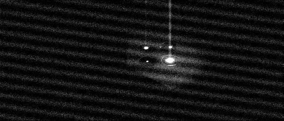
Figure 1

Correction Algorithm
Pat Murphy at APL devised an algorithm which performs an iterative
process to reconstruct the original unsmeared image from the smeared
image read out from the detector. The following describes the basis
for her algorithm.
First, consider how light intensities are measured on the detector. Assuming that a pixel has linear response with exposure time, the signal at a pixel is given by:
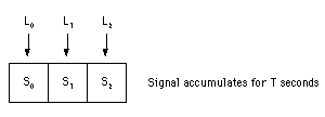
Observed signal = (light intensity * exposure time) * pixel gainConsidering a hypothetical system which consists of three pixels, the accumulation of signal over an exposure time of T is illustrated by the following diagram:
light intensity = electrons / second
exposure time = seconds
pixel gain = DN / electrons

S0 = (L0 * T) * G0In a frame transfer system, half of the detector is physically masked off so that light cannot accumulate on the underlying pixels. This is necessary because the time that it takes to read values out of the detector can be quite long (~1 sec) relative to a short exposure time, however values can be shifted from one cell to another quite rapidly. Therefore, a frame transfer system shifts all the values from the photoactive cells of the detector to the masked cells very quickly, and then slowly reads the values out of the masked cells.
S1 = (L1 * T) * G1
S2 = (L2 * T) * G2
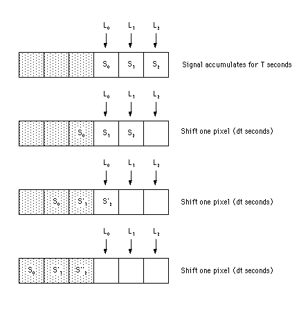
Figure 2 extends the three pixel system above
to show how it would operate as a frame transfer device. This figure
assumes that the original exposure time is T seconds and that
the device can shift the pixels every dt seconds.
Figure 2

Once the values have been shifted into the masked cells, the process which reads the values out can be slow without concern of additional light accumulating on the cells. The main drawback of this approach is that during the shifting operation, additional signal is being added to each of the original values. Figure 2 shows that once the original values have reached the masked off area of the detector, the new values are given by:
S0' = S0
S1' = S1 + [(L0 * dt) * G0]
S2''= S2 + [(L1 * dt) * G1] + [(L0 * dt) * G0]
The additional signal that is added to each original value as it is shifted through the detector is what shows up as the smear in Figure 1. By rearranging the above equations it is possible to reconstruct the original values from the smeared output values, the exposure time, and the line transfer time:
  S0 = [(L0 * T) * G0] = S0'

  S1 = [(L1 * T) * G1] = S1' - [(L0 * dt) * G0]
                       = S1' - [S0 * (dt / T)]

  S2 = [(L2 * T) * G2] = S2'' - [(L0 * dt) * G0] - [(L1 * dt) * G1]
                       = S2'' - [S0 * (dt / T)] - [S1 * (dt / T)]
                       = S2'' - [(dt / T) * (S0 + S1)]
These equations show that the general equation for reconstructing
the original signal values is given by:
S(k) = smeared S(k) - (dt/T)*sum[S(0..k-1)]Since it is assumed that S(0) is not smeared, then the smeared S(1) can be used to compute the unsmeared S(1) which in turn can be used to compute the unsmeared S(2), etc. In order to implement the algorithm for correcting MSI images, the line transfer time must be known and is given by:
number of active lines = 244Using this line transfer time, the following algorithm performs the iterative process necessary to remove the smear from MSI images:
total time to transfer active lines = 0.9 msec
line transfer time = 0.9 msec / 244 lines = 0.0036885 msec/line
	scale = (0.9 / 244) / exposure
	sum = 0
	for k = 1, nrow-1
		sum = sum + [scale*row(k-1)]
		row(k) = row(k) - sum
	endfor
From the equations shown above for S1' and S2'' it has
been shown that the smeared signal values have the gains from multiple
pixels convolved into them. Once the smear correction step has been
applied, the resulting values only have the gain from the original
pixel left in them. Therefore, smear correction must be applied
prior to the flat correction step.
Example
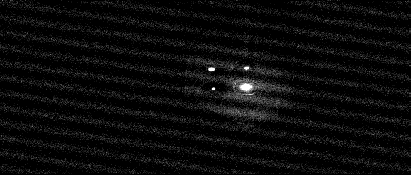
The above algorithm was applied to the same image illustrated in
Figure 1. The resultant smear corrected image is
displayed in Figure 3. Note how efficient the
algorithm was at removing the large smearing which was evident in the
upper right pinhole image.
Figure 3

Availability
Mark Robinson has trimmed down Pat's original IDL script for inclusion
into the standard set of IDL scripts for processing NEAR images.
Mark's IDL script is titled msi_smear.pro.