G. E. Danielson, Division of Geological and Planetary Sciences, California Institute of Technology
M. A. Ravine and T. A. Soulanille, Altadena Instruments Corporation
The Mars Observer Camera (MOC) consists of three integrated optical sub-assemblies (one Narrow Angle and two Wide Angle cameras) with common electronics, designed to take high spatial resolution pictures of the surface of Mars and lower spatial resolution, synoptic coverage of the planet's surface and atmosphere. It incorporates several advanced technologies, including the use of graphite/epoxy structural materials, 32-bit microprocessors, 108-bit digital buffers, and high-speed custom integrated circuits. The cameras use the "push-broom" technique to build pictures, one line at a time, as the spacecraft orbits the planet. The Narrow Angle camera can acquire images of areas ranging from 2.9 km X 2.9 km to 2.9 km X 25.2 km at a resolution of 1.4 m/pixel. Additionally, lower resolution pictures (to a lowest resolution of about 11 m/pixel) can be acquired through the Narrow Angle camera by pixel averaging; these images can be much longer, (up to 2.9 X 500 km at 11 m/pixel). The Wide Angle cameras are capable of viewing Mars from horizon to horizon and, in a single 24-hour period, can acquire a complete global image of the planet at a resolution of at least 7.5 km/pixel. Regional areas (covering hundreds of km on a side) may be photographed at a resolution of better than 250 m/pixel at the nadir. The two Wide Angle cameras images through a different spectral filter, allowing the construction of color images. The MOC is a cylinder 88 cm in length and about 40 cm in diameter; the redundant electronics, equivalent in complexity and computational power to two engineering workstations, fit within a volume 40 cm in diameter and 10 cm long behind the Narrow Angle primary mirror. NASA's Mars Observer mission has adopted a distributed operations philosophy: all uplink and downlink activities for the MOC and the other payload experiments will occur remote from the Jet Propulsion Laboratory's command centers. Following its year-long flight to Mars (launch is scheduled for 16 September 1992), Mars Observer is planned to acquire data for one Mars year (687 Earth days). During that time, MOC will acquire about 2 X 10^12 bits of image and engineering data. During the last three months of the mission, Mars Observer will use a French-supplied relay system to acquire an additional 2 X 10^9 bits of data from balloons deployed as part of the Soviet Mars '94 mission. These data will be collected and transferred to the Earth through the MOC electronics.
Regional weather is displayed as large-scale patterns that rotate with the planet. Over a day, uniform sampling in longitude around the entire globe can allow separation of longitudinal averages from local eddies, and could permit the contribution of each to global transport to be estimated. Daily maps can reveal both meteorological variability as well as longer-term (seasonal) trends. The observational requirement is to globally monitor clouds, hazes, winds, dust, and surface albedo patterns on scales better than the atmospheric scale height (about 10 km) and over a range in timescales from hours to years.
In order to track clouds as a means of determining wind velocities, the distance of one pixel projected on the surface must be no more than one half the desired accuracy of the wind measurement times the interval between measurements. With a time interval of about two hours (the Mars Observer orbit period) and a desired velocity accuracy of 2 m/s, the required resolution at Mars is about 7 km/pixel.
Daily global monitoring for several weeks during the season when dust storms are expected to begin is needed to capture the life cycle of such storms. Of special interest would be such observations of the development of a global dust storm. The scale of such observations should permit detection of initial dust ejection effects as well as track the onset of storm growth (using cloud-tracking). Again, a resolution of about 7 km/pixel is adequate for initial monitoring, although higher resolution would be useful as soon as a storm is detected.
Polar cap recession rates average about 1 km/day, but the polar cap edge is irregular owing to the effects of topography and other surface properties. Identifying the processes that control polar cap recession requires images on the scale of the topography and surface heterogeneities. There is no single scale that dominates these variations, but other instruments on the Mars Observer mission-the Thermal Emission Spectrometer (TES) and the Pressure Modulated Infrared Radiometer (PMIRR)-will be mapping the surface at a few to ten km resolution. The requirement for imaging the polar cap edge is therefore to match or exceed the resolution on which surface properties are measured by other instruments. Medium resolution targeting of the polar cap edge on several successive days is required to reveal changes of order 1 km/day.
Other phenomena such as the polar hood, lee wave clouds, surface wind streaks, and some fogs and hazes occur at certain well-defined times (both diurnal and seasonal) and places. These phenomena have not been monitored on a daily basis. Little is known about day-to-day variability, correlation with passing weather systems, and dependence on humidity, dust activity, or wind speed. The observational requirement is to perform such monitoring at specific locations at medium resolution several times during the Mars year.
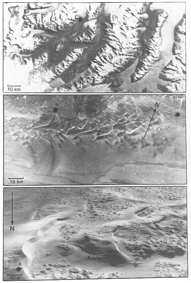
Figure 1: Effects of resolution on problems addressed by imaging. (Top) Landsat view of the ice- free (Dry) valleys of Southern Victoria Land centered at 77.5 S, 162 E, has a resolution of 80 m/pixel, roughly analogous to Viking resolution of Mars. The glaciated valleys and alpine and ice sheet glaciers are clearly visible in this satellite view, but the exact nature of the valley floors is not, nor are the sedimentary products of the glaciations (which are crucially important to deciphering the past glacial history of the area). (Middle) Aerial photograph taken from roughly 25,000 ft above the ground, having a resolution of about 4 m. A dune field (Black Arrow, unlabeled) can be seen moving from east to west across a valley floor dominated by fine sediments experiencing freeze/thaw activity. The chronology of recent events in the valley is clearly seen. From an image of this type, details of the predominating processes, their timescales, and effects on the surrounding terrain, are visible and interpretable. (Bottom) Low level, oblique photograph taken at low sun elevation, showing a portion of the dune field (Black Arrow, "A") at roughly 20 cm resolution. This image shows the interaction of the sediments to create a complex geomorphic scene. Among the features displayed in this image are sand and ice wedge polygons, dunes with frozen, interbeded layers of ice, and patches of rock hummocks on patterned ground showing an equilibrium in boulder distribution (indicating equilibrium between sediment source supply and throughput). MOC will acquire images about a factor of two better than the center photograph, while the Soviet Mars '94 balloons will acquire images roughly comparable to the lower photograph.
Given the constraints of the Mars Observer mission, it is impractical today to cover much of Mars at 1 m/pixel. Fortunately, it is not necessary to do so. One of the lessons learned from the highest resolution Viking images is that contiguous swaths of extremely high resolution data do not often show large changes from frame to frame. This is not surprising, since the scale over which geological processes operate are rarely as small as a single or few images (<=10's km). At high resolution, then, it is necessary only to sample a representative area. Similarly, Viking high resolution coverage showed that one could not predict on the basis of "normal" Viking resolution what would be seen at the highest resolution (Figure 2). There was also little correlation between what was seen by the Viking Landers and what was viewed from orbit. A judicious sampling program, combining elements of random selection with elements of uniform coverage and occasional targeting, at a resolution that bridges the gap between the presently available orbital observations and present and future near-surface data, offers an excellent opportunity to address many of the outstanding problems in martian geology.
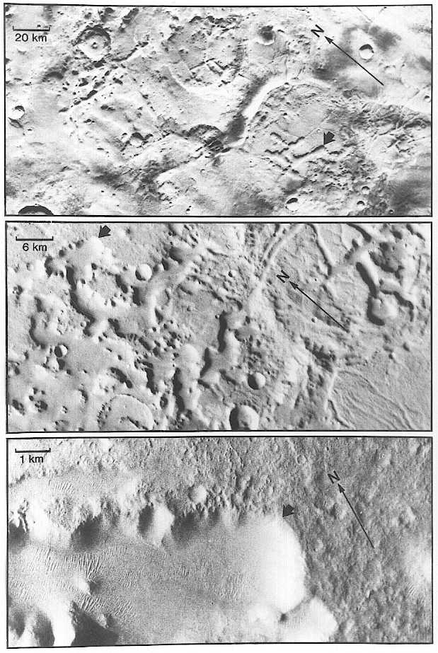
Figure 2: Differences in martian surface appearance as a function of resolution. This figure shows the differences in the martian surface as seen at three different resolutions. A small black arrow indicates a feature seen in all three of the images in the figure. (Top) Area between Al-Qahira and Ma'adim Valles (15 S, 190 W), in the highly disrupted margin between martian heavily cratered and lightly cratered terrains, at a resolution of about 300 m/pixel. (Middle) Portion of area in (Top) at ~70 m/pixel, the resolution representative of much of the better Viking Orbiter coverage of Mars. (Bottom) Portion of (Middle) at theoretical resolution of 11 m/pixel (although it displays evidence of a small amount of image motion smear). Note that at each resolution different aspects of the surface geology are portrayed--it is not possible to predict from images at one resolution what will be seen at higher resolution.
As presented in the Announcement of Opportunity, the Mars Observer spacecraft had several areas of resource limitation that were critical to the design of the MOC. Total payload mass was limited to about 85 Kg, and total power was about 90 W. The minimum payload data rate was 1500 bits per second (1.5 Kbps), and the maximum rate was 6 Kbps. The MOC design team established a set of goals for the design of the camera based on an assessment of the availability of these resources for an imaging system: 10 Kg mass, 5 W power, and 150 bps. These values represented a substantial reduction over previous planetary imaging systems (e.g., the Viking Orbiter cameras weighed 40 Kg, used 46 W, and operated at 8 Kbps; see, e.g., Reilly et al. - this issue). In order to achieve these resource goals while at the same time meeting the requirement to acquire data substantially beyond that available from Viking, a very different design philosophy was used: risk was accepted where in previous experiment designs reduced performance would have been effected. Considerable effort has been made to understand and minimize these risks, but they have, nonetheless, been accepted. To mitigate these risks, the MOC hardware and software design incorporate a philosophy of graceful degradation, wherein considerable operational capability may survive multiple failures. Thus, included within the design are multiple copies of the flight software bootstrap and a polling/voting scheme for its use, bit-error tolerance through the use of error-correcting code (ECC) and continuous refresh of error-encoded information, direct hardware commanding capability without CPU intervention, segregation of electronic memories into independent banks, and redundant and/or cross-strapped electronics. The result is, as will be shown in the following sections, an instrument of remarkable capability.
It was decided that the Wide Angle (WA) camera's field of view (FOV) must extend from limb-to-limb, with approximately 80 km margin at each limb. For mass and complexity savings, a single field-of-view design (i.e., very short focal length "fisheye" optics) was preferred over multiple cameras. The desire to image in two color bands further required two detectors and/or filters, with the associated optimization of optical performance (MTF) then leading to two separate optical systems. The MOC WA cameras were also required to produce higher resolution views of the nadir simultaneously with NA image acquisitions. These "context" frames were required to cover sufficient area to allow reliable recognition and correlation of features within, and hence allow placement with respect to, global Viking coverage. A resolution of better than 300 m/pixel was desired.
After a series of image interpretation experiments, a minimum acceptable signal-to-noise ratio (SNR) of 20:1 was set for a NA target of albedo (A) of 0.10 at an incidence angle (i) of 70 deg, and a WA target of A = 0.10 at i = 80 deg, for Mars at aphelion. In order to achieve the required spatial resolutions of better than 1.5 m/pixel (NA) and 300 m/pixel (WA), the system modulation transfer functions were required to exceed 0.10 at all spatial frequencies below the Nyquist limit.
To match the anticipated low data rates while acquiring NA data at nearly 40 Mbits per second (Mbps), an buffer sufficient to hold several images was needed. As a design point, it was decided that the MOC be able to acquire one 2048 X 2048 NA image while a second was being compressed and/or transmitted to the spacecraft data system. Approximately 1 MBytes (MB) of memory was needed for software and sequencing, and a margin of about 25% was added to assure adequate memory survived the mission. The flexibility of this buffer memory, and the data compression developed to maximize its use, provided the MOC with great flexibility in responding to opportunities to increase its data rate after selection.
The tight power requirements could only be met by power cycling of electronics that weren't actually in use. Thus, it was necessary to segregate the electronics into "power islands" that could cycled independently: the NA electronics could be powered only for brief periods prior to and including NA acquisitions (typically 3 to 5 seconds), and the WA electronics could be turned off during that half of the orbit the spacecraft is in solar occultation. Power cycling, and its attendant thermal effects, are considered by some as increasing the risk of electronics failure, although the actual engineering evidence is, at worst, equivocal.
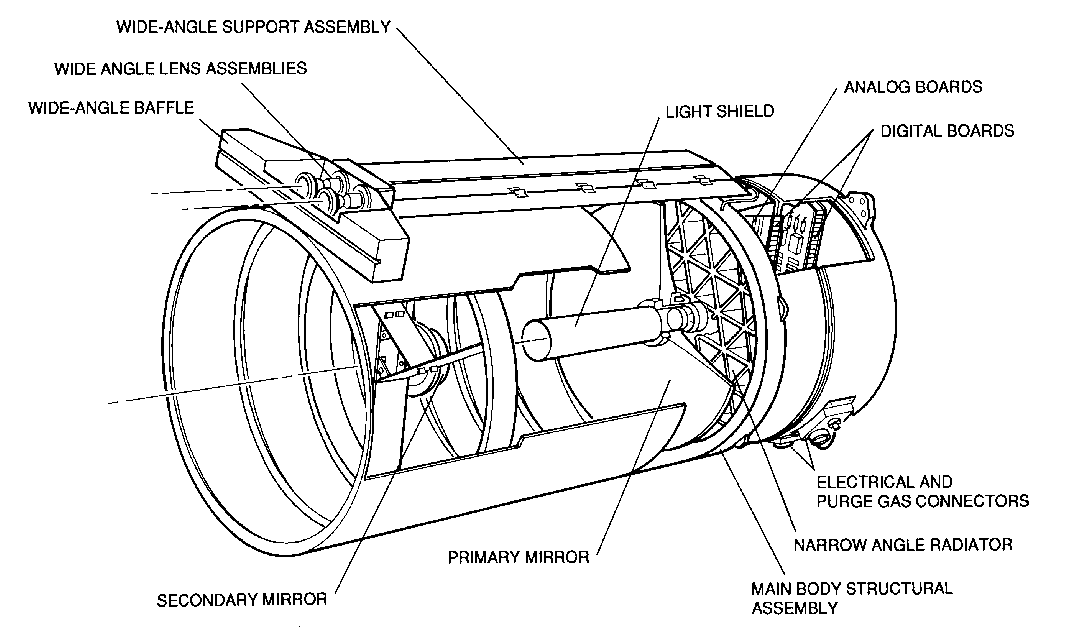
Figure 3: Technical drawing of Mars Observer Camera.
The MOC structure is approximately 88 cm in length and 40 cm in diameter, including four major components (Figure 3). The largest component of the camera is the NA tube (called the Secondary Mirror Support Assembly or SMSA), which holds the secondary mirror spider and acts as both an optical baffle and the primary/secondary distance metering bench. The SMSA is fabricated of pseudo-isotropic P75S/ERL1962 graphite/epoxy in a (0, 45, 90, 135) layup. P75S/ERL1962 graphite/epoxy was selected as the main structural material within the MOC primarily for its high strength and stiffness per unit mass and low density (leading to a low mass) and low coefficient of thermal expansion over a large temperature range (allowing it to maintain focus without active mechanisms or complicated matched-material thermal metering). Attached to the side of the SMSA is the WA assembly, consisting of a mechanical support tube (the Wide Angle Support Assembly, or WASA) also made of P75S/ERL1962 graphite/epoxy with Invar fittings, the two WA optics and focal planes, and a WA baffle. Beneath the SMSA is the P75S/ERL1962 graphite/epoxy Main Body Structural Assembly (MBSA), which supports the primary mirror, NA focal plane and associated electronics, and connects these to the SMSA. Below the MBSA is the electronics assembly, housing three 2-sided electronics boards within an aluminum chassis/radiator assembly, connected to the MBSA by a T300/934 graphite/epoxy conical "flexure skirt."
Owing to the high magnification on the secondary mirror (7.75X) required to fold a 3.5 m focal length into 45 cm (17.8 inches), the NA optics are extremely sensitive to focus: a 1 um shift between the primary and secondary mirrors results in a 60 um movement of the plane of best focus, and the relatively fast optics provides only a 115 um depth of field. Thus, the NA design is extremely sensitive to gravitational, vibrational, and thermal loads, and to moisture absorption, which arises from the hygroscopic nature of the epoxy. Great care has been taken to minimize the effects of temperature variations on the camera. For example, the secondary spider vanes are arranged such that expansion or contraction of their lengths will rotate rather than despace, decenter or tilt the secondary mirror. Adoption of a passive, graphite/epoxy-based structural metering system, and the uncertainties in its performance prior to actual testing of the Flight system, represents one of the principal areas of risk to the MOC experiment.
Owing to their short focal lengths and compact design, the WA optics (each is a 9-element all refractive design) and their titanium housings are relatively insensitive to gravitational, vibrational, and thermal loading.
The MOC optics/structure weighs 9.5 Kg, the primary mirror and its mechanical assembly accounting for 3.4 Kg (36%). The primary mirror has been lightweighted and sags slightly under its own weight in a one-g field. The WA lenses and housings, and the NA secondary mirror and its housing, together weigh 0.6 Kg. The graphite/epoxy structures and associated fittings weigh 3.5 Kg, and the aluminum electronics housing and radiator and miscellaneous hardware, weigh 2.0 Kg.
Telkamp and Derby [3] have published a more technical description of the MOC optics and structure, as well as details of the design analysis and testing results of the MOC Engineering and Flight Models.
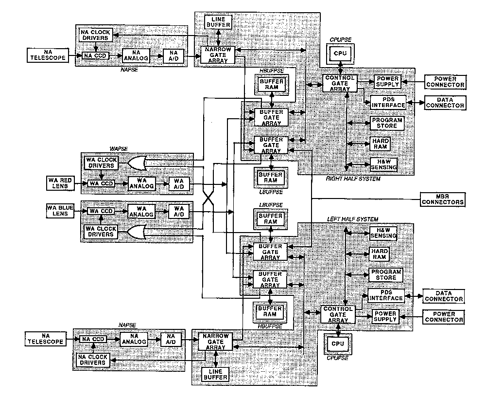
Figure 4: Functional block diagram of Mars Observer Camera.
In order to meet the noise and other performance requirements, two custom CCDs were fabricated for the MOC by Ford Aeronutronics (now Loral Aeronutronics): one for the MOC NA (2048 13 um pixels, two outputs) and one for the MOC WA (3456 7 um pixels, one output). Development work also resulted in devices with thinner polysilicon layers than used in Ford's standard process, increasing their quantum efficiency in the blue (400 to 450 nm).
The custom CCDs are individually packaged and mounted on custom hybrid ceramic substrates. Each hybrid is attached to a small printed circuit board (PCB) that contains a small amount of pre-amplification circuitry inside the radiation shielding to minimize low level signal path lengths. The hybrid and PCB are mounted together in a focal plane assembly that provides mechanical alignment of the detector to the optics, radiation shielding of the detector (down to <1 kilorad for the NA, <2 kilorad for the WA), and thermal control. Each FPA has a heater to keep it warm during the cold cruise to Mars, and each incorporates a thermal path to conduct away heat produced during operation. In the case of the NA, the thermal path runs from the FPA to an "internal radiator" behind the primary mirror. This radiator loses its heat by radiation to the back of the primary mirror which, in turn, loses heat by radiation to Mars during the nominal mission, or to space during interplanetary cruise. The focal plane assemblies are attached to the main analog circuitry through flex cables with multiple isolated return paths to minimize cross-talk.
Based on breadboard measurements, the NA signal chain has a readout noise is less than 70 electrons, and a dark current noise of less than 3 electrons rms at its operating rate. The WA signal chain has a readout noise of less than 15 electrons, and a dark current noise of less than 25 electrons at WA operating rates. In-band quantum efficiency for the NA detector (i.e., between 500-900 nm) is better than 35%, for the WA red detectors (575-625 nm) better than 35%, and for the WA blue detectors (400-450 nm) better than 10%. Both detector designs have charge transfer efficiencies better than 0.999995.
Combined with the optics described in the preceding section, the 2048 X 1-element line array with 13 um pixels provides permits a NA resolution of 1.41 m/pixel from 380 km altitude and better than 1.5 m/pixel over the entire range of operational altitudes, while the WA cameras, using the 3456 X 1-element line array with 7 um pixels, achieve nadir resolutions of 233 m/pixel (blue) and 242 m/pixel (red) from 380 km altitude.
Correlated double sampling (CDS) is implemented in both cameras to attenuate reset and low-frequency noise. In the WA this is performed by the fairly conventional means of using two separate sample and hold circuits, one holding the reset level and the other the video level, both driving the inputs of a difference amplifier. Owing to the high speed of the NA (each of the two NA CCD outputs produces pixels at 400 ns intervals), a 200 ns delay line comb filter is used in each output chain to form the difference between the reset and video period, and this difference is further filtered and sampled before the offset and A/D operation.
All variable gain is taken before the CDS, while the signal is effectively "chopped," providing immunity from offset drift in these amplifiers. Monolithic transimpedance amplifiers are extensively used in the NA for their compactness and high-frequency performance. A slow feedback loop maintains the average reset level of the signal at a fixed voltage, keeping the reset and video levels in a stable, linear range of the amplifiers while the clock feedthrough transients are removed by clipping stages to keep the amplifiers out of saturation.
For each of the NA and WA, dual-tracking linear field effect transistor-series regulators, operating with about 300 mV of headroom, provide overall post-regulation and ripple rejection for the analog 10 V power rails. L-C-R decoupling is used to isolate individual amplifiers. These regulators provide overcurrent power cycling and current monitoring to the housekeeping telemetry. They operate as switches to shut down the analog load by microprocessor command,to conserve power.
Both NA and WA analog systems show long-term gain stability of better than 1% and gain stability over temperature excursions of better than 0.5% per 10 deg C. The NA system uses about 700 parts and draws about 3 W; each of the WA systems uses about 450 parts and draws 1 W. Noise through the WA analog system is 25 electrons, while noise through the NA analog system is less than 80 electrons.
The MOC "slow digital" electronics include the power supply, bus interface unit (BIU), housekeeping/engineering measurement circuitry, and power switching elements (PSE). The power supply consists of two flyback-type switching converters, each capable of operating asynchronously at approximately 45 KHz but normally synchronized to a common 50 KHz clock. Both converters share a common input filter. One converter (the "digital" converter) operates whenever the spacecraft-provided 28 VDC bias is present. It provides +5 V to the digital logic and +20, +10 and -10.5 V to various sensitive analog loads (for which separate return lines are maintained). The second converter (the "analog" converter) also draws from the spacecraft 28 VDC power, but may be turned off using secondary control logic. It supplies only analog referenced voltages: +22.5, +10.5, -10.5, +12, -5, and -20 V.
Voltages from each of two "slow digital" boards are "diode or'd" to provide power redundancy to the analog and digital systems.
The bus interface unit is Mars Observer Project-provided hardware that acts as the link between the MOC and the spacecraft Payload Data Sub-System (PDS). Three functions are accomplished by the BIU: 1) it receives MOC uplink commands from the PDS (in the form of a serial bit-stream that is converted by the BIU to a 16-bit parallel format at the BIU/MOC interface), 2) it requests and receives from the MOC science and engineering data in 16-bit words on specific polling schedules, and 3) it provides a spacecraft timing reference signal (the Real-Time Interrupt, RTI) eight times a second. The PDS to BIU link is Manchester II encoded, and the BIU incorporates a custom encoder/decoder chip to decode commands. All three signals are carried over shielded differential twisted wire pairs.
MOC housekeeping/engineering monitoring occurs for 48 points within each redundant system--34 voltages and currents and 14 temperatures. Test points are selected using analog switches; the voltage from a selected test point is fed to a voltage controlled oscillator (VCO) which is allowed to settle for two output cycles. VCO cycles are counted by an A/D converter, with sampling initiated on an integer RTI and completed one RTI later. The final count may be read immediately thereafter. Housekeeping telemetry is sampled four times each second.
Owing to power constraints, the MOC implements power management circuity. Power switching elements permit various sections of the MOC digital and analog electronics to be power-cycled to reduce orbit-average power consumption. Some of these elements also incorporate circuitry to sense overcurrents that result from cosmic-ray induced single-event latchups (SEL). Power-cycling these sections enables the MOC electronics to avoid the deleterious effects of such latch-ups.
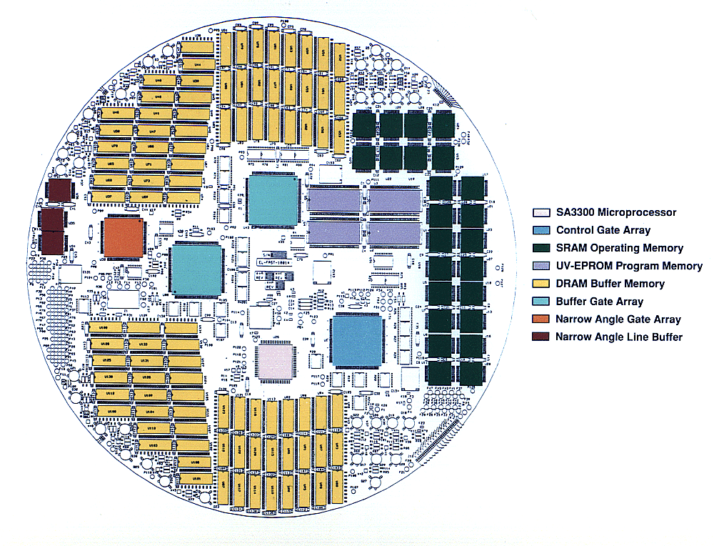
The MOC control system is based on a radiation-hard version of the National Semiconductor 32C016 microprocessor developed by Sandia National Laboratories (the Sandia SA3300). The SA3300 is a 32-bit microprocessor with a 16-bit bus and a 24-bit address space. The MOC operates its SA3300 at 10 MHz, giving a computational performance of just under 1 MIPS. Among the advantages of this processor is that all flight software could be written in a high level programming language ("C"). All memory and control registers are located in the logical address space of the microprocessor. All of its address space is also directly accessible by ground command through the PDS by direct memory load.Figure 5: Layout of MOC "Fast Digital" Board. Pink SA3300 microprocessor Blue Control Gate Array Purple UV-EPROM Program memory (4 32-KB devices = 128 KB) Dark Green SRAM Operational memory (24 8-KB devices = 192 KB) Yellow DRAM Buffer memory (98 1-MB devices in 2 banks = 12 MB) Light Green Buffer Gate Arrays (2) Orange Narrow Angle Gate Array Brown NA Line Buffer memory (3 8-KB devices = 24 KB)
All of the MOC digital design except the microprocessor, memory, and BIU is implemented in gate arrays. Three basic designs are used, with two occurring on the same chip. The three designs are called the Control Gate Array (CGA), the Buffer Gate Array (BGA), and the Narrow Angle Gate Array (NAGA). Four parts (1 CGA, 2 BGA, and 1 NAGA) are used in each of the redundant half-systems.
The CGA provides the link between the SA3300 microprocessor and the rest of the system by performing all address decoding and memory mapping. It incorporates interfaces to the program memory and operational memory, three direct memory access (DMA) channels to the BIU, and the housekeeping/engineering VCO. It also includes the reset/bootstrap controller and "deadman" timer. The CGA permits direct memory/register access without CPU intervention, allowing the MOC to continue to function should its microprocessors fail during the mission, albeit in a degraded fashion.
The BGAs provide DRAM interfaces to each of two separate "banks" consisting of 6 MByte each. Each BGA also provides WA CCD clocking, analog setting control, and downtrack summing for one of the two WA cameras, as well as WA data DMA. Each BGA allows data DMA for both the Mars Balloon Relay (MBR) link and the NA camera, and applies ECC to the MBR data.
The NAGA provides acquisition control and image processing capabilities for the NA camera. It generates the NA clocking and acquisition control signals. Image processing capabilities include cross-track summing, and one- and two-dimensional predictive compression, resampling, and Huffman encoding. All data acquired through the NAGA may be optionally impressed with a 16-bit polynomial ECC syndrome capable of correcting 2 bit errors in 256.
Each of the MOC's two half-systems incorporates more digital memory than has cumulatively flown on planetary missions: ninety-six 1 Mbit DRAMs arranged in two banks of 3 million 16-bit words each. The primary use of this memory is image storage and downlink data rate buffering, although approximately 1 MByte is allocated for flight software use (e.g., command sequences, scratch space, etc.). Access bandwidth to the RAM buffer is sufficient to accommodate NA, WA, and MBR acquisitions, and memory refresh and PDS DMA transfers, all simultaneously and at their maximum rates. CPU accesses are given lower priority and are delayed as necessary to allow other system activities the access they require.
The DRAM devices are susceptible to both cosmic-ray induced single event upset and latchup (SEU and SEL). Based on tests performed by the MOC design team, SEUs will probably occur less than 100 times each day under normal solar conditions. The ECC applied to information stored in the DRAM was designed to repair such data corruption; the software refresh rate is selectable to match the actual upset rate. Such procedures will not work during energetic solar flares, but these are expected to occur rarely during the Mars Observer mission. Additionally, every set of three devices (i.e., one bit in the 16-bit word) has a separate power sensing element capable of detecting SEL-induced overcurrent, and power-cycling those parts. As these devices use capacitive storage, the short-duration power-cycles are non-destructive (i.e., the memories retain their contents).
The MOC includes two other memory banks--one each for program memory and operational memory. The program memory consists of 128 KBytes of ultraviolet-erasable programmable read-only memory (UVEPROM), while the operational memory consists of 192 KBytes of radiation-hard static random access memory (SRAM). The flight software is stored in the UVEPROM, with ECC. It is copied into the SRAM for execution. A small amount of SRAM is also used as a high-speed line buffer for the NAGA.
WA commanding constitutes the most complicated task of the flight software. Owing to the desire to simultaneously acquire global monitoring, NA context, and local and regional WA coverage, a schema of "virtual cameras" was implemented. The BGA incorporates a 16-line "ring buffer" into which WA observations are continuously acquired on each sun-lit pass; the flight software routes lines from this buffer to separate addresses, each representing a different acquisition or "camera." Downtrack and cross-track summing can be performed separately from full-resolution acquisitions. Different pixel positions along the detectors may also be selected so that, for example, both nadir "context" frames and limb observations can be acquired at the same time without returning to Earth the full 3456 pixel FOV.
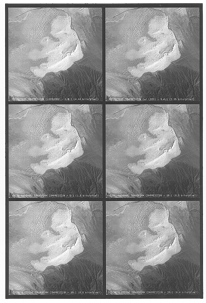
Figure 6: Example of data compression techniques to
be employed on Mars Observer Camera. (Landsat TM 5/1138/17/45 Band 1
Partial Frame).

UL: Lossless 2-D Predictive (1.8:1)	UR: Lossy 2-D Predictive (3.5:1)
ML: Walsh-Hadamard Transform (5:1)	MR: WHT (10:1)
LL: Discrete Cosine Transform (10:1)	LR: DCT (20:1)
The fields of view of both the NA and WA cameras, the nature of the Mars Observer spacecraft and mission, and specific aspects of the MOC design place certain constraints on viewing Mars. The width of MOC NA frames is limited by the camera FOV to be about 2.9 km. Even if Mars Observer orbits were uniformly spaced, it would take over 600 days for the same location near the equator to be viewed twice. Given the 687 nominal mission duration and the vagaries of the Mars Observer orbit that result from gravitational perturbations and atmospheric drag, MOC will be fortunate to pass over each equatorial area once. At higher latitudes, of course, the number of opportunities to image a given location increases. Unfortunately, the along- and cross-track orbit prediction uncertainties are larger than the NA FOV owing to mission operational constraints on Earth. Thus, targeting a given feature will be a probabilistic activity. Contiguous "mosaics" of NA images are not possible. The WA FOV covers approximately 1300 km on the surface from nadir to each limb. At the equator, Mars Observer orbits are spaced about 1500 km, so the limb on one orbit is at the nadir on the subsequent orbit, and again at the limb on the orbit after that. There is therefore good overlap at the equator, and excellent overlap closer to the poles. Contiguous WA mosaics are possible.
MOC image sizes are determined by the camera FOV (cross-track dimension, as noted above) and by the size and utilization of the 12 MB digital buffer (along-track). Using realtime compression, it is possible to acquire an image longer than the orbit determination along-track uncertainty. However, other contents of the buffer may prevent its use in this manner. Buffer space is thus an important resource that requires close management. For this reason, MOC images can vary in size and compression factor. For the NA, areas ranging from 2.9 km X 2.9 km to 2.9 km X 25.2 km (depending on available buffer memory) can be imaged at about 1.4 m/pixel. Additionally, lower resolution pictures (to a lowest resolution of about 11 m/pixel) can be acquired by pixel averaging. Contingent as well upon available power, these images can be much longer, ranging up to 2.9 X 500 km at 11 m/pixel.
Since payload selection and the Mars Observer project "new start" in 1986, the data return from Mars Observer has grown significantly with better understanding of the spacecraft and ground telecommunication system. Mission data rates, and the MOC data rate allocation, vary substantially over the course of the Mars Observer mission, owing to Deep Space Network link performance. They include recording at 3.5, 7, and 14 Kbps, and transmitting in realtime at 34.2 Kbps. MOC data rates vary from 0.7 Kbps during the lowest record rate to 9 Kbps during the highest record rate, and 29 Kbps during realtime transmissions. These rates permit the daily transmission of roughly 2, 4, and 8 uncompressed 2048 X 2048 images during "record only" days and, once every three days, 14 such images during an eight hour realtime pass. These numbers can be larger or smaller, depending on the compression factors used and the resolution of the global map that is being acquired at the same time. MOC is capable of simultaneously sending data to both the record and realtime streams, and is further capable of matching any data rate available on-board the spacecraft.
MOC sequence design is based on the desire to image two types of targets: those that are time-independent and those that are variable. In both cases, the targets will be entered into the MOC operational data base. Targets will be identified by position on Mars, and include additional ancillary data necessary to specify most of the "event" or E-file information about each observation (e.g., type of target, science objective, etc.). For each target, an observational strategy will be developed and included in the E-file, specifying, for example, the image size and shape optimized for science coverage, and repeat cycle intervals for WA regional coverage. Targets will be sorted by occurrence along the predicted orbits. Initial sequences of accessible targets will be created from the list of targets that occur along the predicted orbits and within a tolerance of possible deviations from those orbits. The sequence will then be evaluated against the available downlink data rate. Representative, multi-day sequences will be produced and uplinked to the spacecraft. These sequences will be re-evaluated whenever better orbit predictions are available, and necessary changes will be uplinked.
In operation, the MOC treats MBR acquisitions as if the MBR were another camera system. Commands are sent to the MOC to establish the time and data volume for a given balloon relay pass. Simultaneous image acquisitions are possible, providing a framework for the balloon data. The balloon data are error encoded prior to transmission to the MBR; MOC also places on the data and refreshes an ECC. The balloon data, MBR engineering data, and doppler measurements are all placed in MOC data packets and transmitted to Earth in the normal Mars Observer data stream. The data are delivered to the MOC operations facility where they are decoded and analyzed, and additionally transmitted to the French and Soviet mission operations centers.
[2] Malin, M. C., G. E. Danielson, A. P. Ingersoll, H. Masursky, J. Veverka, M. A. Ravine, and T. A. Soulanille, The Mars Observer Camera, submitted to J. Geophys. Res. (1991).
[3] Telkamp, A. R. and E. A. Derby, Design considerations for composite materials used in the Mars Observer Camera, in Advances in Optical Structure Systems (J. Breakwell, V. L. Genberg, and G. C. Krumweide, ed.) Proc. Int. Soc. Optical Eng. (SPIE), 1303, 416-436 (1990).
	Focal length			3.5 m
	Aperture			0.35 m
	Focal Ratio			f/10
	Angular Field of View		7.7 mr (0.44 deg)
	Instantaneous FOV		3.7 microrad (0.76")
	Resolution @ 380 km		1.41 m/pixel
	Swath Width (pixels)		2048
	Swath Width @ 380 km		2.9 km
	Signal-to-Noise Ratio		20:1 for A~0.1, i~70 deg,
					at aphelion
	CCD Readout Noise		< 50 electrons at -20 deg C
	Line Time			0.44 ms
	Radiometric Accuracy		<10% absolute, <3% relative
	Spectral Bandpass		500 nm to 900 nm
	Geometric Accuracy		better than 2%
	System MTF			> 0.1 at all frequencies below
					Nyquist
					(38.5 line pairs/mm)
	Focal Length			11.0 mm
	Entrance Pupil			1.7 mm
	Focal Ratio			f/6.4
	Angular Field of View		2.44 r (140 deg)
	Instantaneous FOV		0.64 mr (2.2')
	Resolution @ 380 km		242 m/pixel
	Swath Width (pixels)		3456
	Swath Width @ 380 km		limb+80 km to limb+80 km
	Signal-to-Noise Ratio		20:1 for A~0.1, i~80 deg, at
					aphelion
	CCD Readout Noise		< 30 electrons at -20 deg C
	Line Time			75 ms
	Radiometric Accuracy		10% absolute, 3% relative
	Spectral Bandpass		575 nm to 625 nm
	Geometric Accuracy		better than 2%
	System MTF			> 0.1 at all frequencies
					below Nyquist
					(71.4 line pairs/mm)
Focal Length 11.4 mm Entrance Pupil 1.8 mm Focal Ratio f/6.3 Angular Field of View 2.44 r (140 deg) Instantaneous FOV 0.61 mr (2.1') Resolution @ 380 km 233 m/pixel Swath Width (pixels) 3456 Swath Width @ 380 km limb+80 km to limb+80 km Signal-to-Noise Ratio 20:1 for A~0.1, i~80ˇ, at aphelion CCD Readout Noise < 30 electrons at -20 deg C Line Time 75 ms Radiometric Accuracy 10% absolute, 3% relative Spectral Bandpass 400 nm to 450 nm Geometric Accuracy better than 2% System MTF > 0.1 at all frequencies below Nyquist (71.4 line pairs/mm)
	Mass				23.6 Kg (including
					redundant electronics)
	Power				6.7 W standby, 9.5 W
					acquiring Wide Angle
					only, 18.7 W when
					acquiring Narrow Angle
	Physical Dimensions		88 cm long by 40 cm
					diameter cylinder
	Data Rates			0.7, 2.856, 9.12 Kbps
					(record only); 29.26 +
					1.388, 4.52, 10.782 Kbps
					(realtime + record)
	Processor Speed			10 MHz, ~1 MIPS, 32-bit word
	DRAM Image Buffer Memory	12 MBytes
	SRAM Operational Memory		192 KBytes
	UV-EPROM Program Memory		124 KBytes
	Data Compression 		~1.5:1 for predictive
					lossless compression
					~5:1 with transform
					compression with loss
	Bit Error Rate			MOC contribution <10-6
Science Team
	Principal Investigator		M. Malin (Arizona State University,
					Tempe, AZ)
	Co-Investigators		G. E. Danielson (Caltech, Pasadena, CA)
					A. Ingersoll (Caltech, Pasadena, CA)
					H. Masursky, deceased (U. S. Geological
					Survey, Flagstaff, AZ)
					L. A. Soderblom (U. S. Geological
					Survey, Flagstaff, AZ)
					J. Veverka (Cornell University,
					Ithaca, NY)
Instrument Manager			G. E. Danielson (Caltech, Pasadena, CA
System Engineering			Altadena Instruments (Pasadena, CA)
Optics/Structure
	Principal Contractor		Optical Corporation of America (OCA)
					Applied Optics (formerly Perkin-Elmer
					Applied Optics, Garden Grove, CA)
	Graphite/Epoxy Structure	Composite Optics, Incorporated
					(San Diego, CA)
Focal Plane Assemblies
	Design				Altadena Instruments (Pasadena, CA)
					D. Harrison (Caltech, Pasadena, CA)
	CCD Detectors			Ford Aeronutronics (now Loral
					Aeronutronics, Newport Beach, CA)
	Hybrid packaging		MicroHybrids, Inc. (Medford, NY)
Analog Electronics
	Design				C. Hansen (Questel, Inc., Grass
					Valley, CA), Electronic Design
					Associates (Costa Mesa, CA)
Digital Electronics
	Design				APh Technological Consulting
					(Pasadena, CA)
					Altadena Instruments (Pasadena, CA)
	Microprocessor			National Semiconductor (San Jose, CA)
					and Sandia National Laboratories
					(Los Alamos, NM)
	ASIC				United Technologies Microelectronics
					Center - UTMC (Colorado Springs, CO)
	Buffer DRAM			American Telephone & Telegraph - AT&T
					(Allentown, PA)
Power Supply
	Design				G. P. Engineering (Oceanside, CA)
Electronics Assembly
	Production Management		T. Cushing (Caltech, Pasadena, CA)
	Board Design			R. Applewhite (Caltech, Pasadena,  CA)
					Composite Optics, Inc. (San Diego, CA)
	Board Assembly and Test		Loral-EOS (Pasadena, CA)
Software
	Flight Software			K. Reinholtz, T. Ligocki, V. Choate
					(CommPower, Inc., Agoura Hills, CA),
					M. Caplinger (Arizona State University,
					Tempe, AZ)
	Ground Support Equipment	S. Brylow (Caltech, Pasadena, CA)
	Ground Data System		M. Caplinger (Arizona State University,
					Tempe, AZ)
 Return to MSSS Home Page