MOC 2's Excellent Adventure Begins...
Fixing the Wide Angle Camera Problem
Table of Contents
The Problem
At about 7:00 PM MST on Friday, 1 December, we began imaging tests of
the MOC 2. By 7:10 PM, we had encountered an anomaly with the Red WA
camera--odd pixels appeared dead while even pixels appeared to be
normally active (both dark current and photoactive). By 7:20 PM,
after trying the Blue WA and getting normal response, and taking
additional Red WA images with the same morphology, we knew we had a
problem. After characterizing the problem, we continued the
"aliveness" imaging tests with the remaining cameras, using both half
systems. Much of the rest of the evening was spent trying to figure
out what was wrong with the Red WA.
 Looking for The
Problem
JPG = 163 KBytes
GIF = 354 KBytes
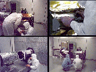
Caption: Looking for the Problem with the MOC 2 Red WA
camera.
Upper Left: Jose and Steve checking the schematics of the flex cable
that carries the signal to and from the Red WA FPA.
Upper Right: Probing the between various leads and grounds.
Lower Left: Steve discussing the problem with MOC.
Lower Right: Steve discussing the problem with QA.
Additional tests were performed Saturday morning (2 December), but
nothing isolated the problem. After running out of options, Jose was
dispatched to Pasadena to gather up test, repair, and replace
equipment and hardware, including the spare FPAs. Steve tried to get
some information through a LMA oscilloscope, but was defeated by that
device. Testing of the NA, as discussed in the preceding section,
continued.
Jose returned Sunday afternoon with a full kit of equipment, including
a MOC oscilloscope. Early Monday morning (December 4), while getting
ready to test with the equipment from Caltech, and preparing to demate
the Red WA FPA, the source of the problem was discovered.
 The
Problem
JPG = 58 KBytes
GIF = 78 KBytes
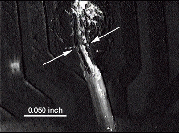
Caption: The Problem.
This figure shows a microscope break in the connection of a small
haywire (one of two for each camera) used to jump from a path in the
flex cable to the connector. The application of conformal coating
material (parylene) had tightened the wire, removing the strain
relief. A hairline fracture developed, probably during transport to
LMA. The conformal coating held the wire in place, making it
difficult to see the detachment at the solder joint.
The decision was made to replace all four haywires.
 Implementing
the Fix
JPG = 149 KBytes
GIF = 297 KBytes
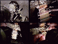
Caption: Implementing the Fix.
Upper Left: Set up of the stereobinocular microscope, with the
connector taped into place for work.
Upper Right: Closeup view of connector (center bottom) and flex cable
(middle) held in place by antistatic tape (shiny grid pattern at top).
Jose is using a tool to attach a small piece of insulating material
over the area to be worked on, to provide protection for the rest of
the cable and connections, and to act as a "work bench" for the
mechanical shaping of the wire and the soldering.
Lower Left: Soldering the new wire into place.
Lower Right: Checking the electrical connectivity of the new
wire.
With the successful repair of the Red WA, testing of the MOC continued
(see previous section).
Back to Setting up in SSB 201
Cleanroom
to MOC 2 ATLO Overview
 Return to MSSS Home Page

