MOC 2's Excellent Adventure Begins...
Installing the MOC 2 on the MGS Spacecraft Nadir Panel
Table of Contents
Testing of the MOC was completed Tuesday night (6 December) around
8:45 PM. The instrument was scheduled to be integrated onto the nadir
equipment deck (NED) of the spacecraft Wednesday night. The plan
called for transporting the instrument to the High Bay at around 3 PM,
practicing the procedure for attaching the handling fixture and
transporting the instrument to the NED, and then, around 8 PM, to
install the MOC.
 The Cleanroom
Ninjas
The Cleanroom
Ninjas
JPG = 177 KBytes
GIF = 417 KBytes
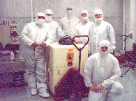
Caption: The MOC Delivery Team (minus 2).
The MOC Team posing with the camera in its shipping container and the
handling fixture ("Jaws," seen at left rear). From left to right, the
team consists of Jose Tamayo (Caltech, MOC Flight Hardware
Technician), Ed Danielson (Caltech, MOC Instrument Manager), Rick
Stiebel (JPL, MOC Quality Assurance Engineer), Mike Malin (MSSS, MOC
Principal Investigator), Mike Caplinger (MSSS, MOC Ground Data System
and Flight Software Design Scientist), and Jeff Warren (MSSS, MOC
Software Engineer). Not pictured are Lynn "Doug" Douglas and Steve
LaBrecque.
The MOC team arrived at LMA mid-morning and began packing for the move
into the High Bay facility. By noon, we were ready to move. The
spacecraft team was ready around 1:00 PM, so the decision was made to
advance the schedule.
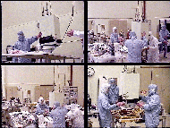
 Preparing to
Install the MOC
Preparing to
Install the MOC
JPG = 177 KBytes
GIF = 417 KBytes
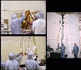
Caption: Preparing to Install the MOC on the NED.
Upper Left: LMA technicians prepare the NED for receiving the MOC.
Since this was a "flight mate," the actual flight thermal
protection/isolation blanket that fits beneath the MOC had to be
prepared and installed, which is the activity shown in this
picture.
Right: The large, overhead crane has attached to it an additional,
special hydraulic fixture (the "Hydra Set," top) that permits precision,
very slow lifting and lowering of objects.
Lower Left: Attaching the cables of the Hydra Set to the empty MOC
lifting fixture.
The crane was then used to raise and lower the handling fixture
("Jaws") above the work table, and the operators practiced the rates
at which they would move the crane once the camera was inside the
fixture.
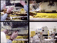
 Encapsulating
the MOC in its Handling Fixture
Encapsulating
the MOC in its Handling Fixture
JPG = 248 KBytes
GIF = 540 KBytes
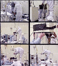
Caption: The MOC is Encapsulated within its
Handling/Lifting Fixture.
Upper Left: Jose and Rick lift the MOC out of its shipping container
and up onto the work table.
Upper Right: Ed removes the "soft cover."
Middle Left: Phil Stapler (LMA), Jose (hidden behind MOC), and Ed (on
ladder) guide "Jaws" over the MOC as Mike Clawson (JPL QA) watches.
Middle Right: Lowering "Jaws" over the upper end of the NA
telescope.
Lower Left: Guiding "Jaws" down the length of the NA telescope.
Lower Right: Ed locks one of the three "knuckles" that grip the
electronics cylinder at the base of the telescope.
 Preparing the
MOC for Integration
Preparing the
MOC for Integration
JPG = 146 KBytes
GIF = 311 KBytes
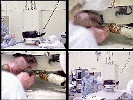
Caption: Preparing the MOC for Integration.
Upper Left: "Jaws," with the MOC inside, is lifted a few inches above
the work table.
Upper Right: The holes in the MOC feet are roughened for better
electrical connectivity and for holding the through-hole bolts that
will affix the MOC to the NED. "Steel wool" is used, with a vacuum
hose near-by to suck up stray particles.
Lower Left: A cleaning/treating solution is applied to the hole.
Lower Right: The MOC is ready to put on the spacecraft!
 Transporting
the MOC over to the NED
Transporting
the MOC over to the NED
JPG = 146 KBytes
GIF = 311 KBytes
Caption: Moving the MOC across the Room.
Upper Left: A view from the floor, looking up at "Jaws" as the crane
begins to move it across the room to the NED.
Upper Right: Passing the MOC across an intervening table (towards the
NED).
Lower Left: Another view of the MOC as it is "handed" across an
intervening table (towards the NED).
Lower Right: Positioning the MOC over its mounting position on the NED
(the +Y, -X side of the nadir panel).
 Attaching the
MOC to the NED
Attaching the
MOC to the NED
JPG = 146 KBytes
GIF = 311 KBytes
Caption: The MOC is lowered and attached to the NED.
Upper Left: Positioning the MOC over the three foot locations. These
pictures provide a good view of the white-thermal-painted electronics
cylinder (which houses the block redundant MOC electronics) and the fitting to which
the N2 purge gas line will be attached (translucent white
plastic with dark fittings and tubing just below lip of "Jaws").
Upper Right: Almost there. The MOC is a few millimeters above the
3/4-inch thermal insulating standoffs to which it mounts. This is a
good view of the purge fitting.
Lower Left: Bolting the MOC to the NED.
Lower Right: "Jaws" and the MOC in position on the NED, awaiting the
arrival of the Thermal Emission Spectrometer (TES). On the opposite
side of the NED from the MOC (i.e., foreground) is the Mars Horizon
Sensor Assembly (MHSA), part of the Attitude and Articulation Control
Subsystem (AACS).
After installation, the MOC was checked out on Friday and Saturday
(8-9 December). Friday was devoted to the Initial Power Turn-On
(IPTO) test, which includes checking each wire in each cable before
powering the camera. The test was completely successful. Saturday
was devoted to the Functional Electrical Test (FET), which exercises
the MOC and its electrical connections to the spacecraft (including
the bakeout and cruise survival heaters). Portions of the test were
run successfully, but problems in uploading the Payload Data System
(PDS) prevented completion of the test. It was finally re-run (with
complete success) on 18 December, with MOC personnel participating
remotely via the NASCOM connection through JPL to LMA.
The MOC now awaits the arrival of the rest of the payload. The next
major activity will be the spacecraft systems tests, roughly in the
March 1996 timeframe.
Forward to Stacking the
Spacecraft Modules and Weighing the MOC Handling Fixture
to MOC 2 ATLO Overview
 Return to MSSS Home Page