-
Introduction
5.1. Mars Capture Sub-Phase
-
5.1.1. Mars Orbit Insertion Maneuver
5.1.2. Post-MOI Capture Orbit Checkout
5.1.3. Spacecraft Configuration
5.1.4. Science Activity During Mars Capture Sub-Phase
-
5.2.1. The Basic Problem
5.2.2. Aerobraking Design and Timeline
5.2.3. Spacecraft Configuration
5.2.4. Science Activity
-
5.3.1. Mapping Orbit Acquisition
5.3.2. Gravity Calibration Period
5.3.3. Spacecraft and Payload Checkout Period
5.3.4. Spacecraft Configuration
5.3.5. Science Activity
Introduction
The orbit insertion phase is the period of transition from the interplanetary trajectory to the mapping orbit around Mars. This phase extends from the beginning of the Mars orbit insertion (MOI) sequence, until the spacecraft is established in the mapping orbit and declared ready to begin science data collection. Due to the length of the orbit insertion mission phase and the number of critical events contained within it, three sub-phases have been defined. The first is the "Mars Capture" sub-phase, which begins with MOI and extends nine days until the start of aerobraking. The "Aerobraking" sub-phase is the phase in which the orbit is reduced from the initial capture orbit down to a "near" 2:00 p.m. Sun-synchronous polar mapping orbit. "Transfer to Mapping" is the final sub-phase, in which the final mapping orbit is achieved and the spacecraft and payload are configured for mapping operations.Figures 5-1 and 5-2 show timelines for the baseline orbit insertion strategy, for a 3 November 1996 launch date and a 24 November 1996 launch date. These dates represent the old open and close dates for the launch period, since the aerobraking trajectory design has not been updated for the new launch period, which has shifted one day later. The last launch date drives the aerobraking design, due to the least amount of time available to reach a 2:00 p.m. orbit.
5.1. Mars Capture Sub-Phase
5.1.1. Mars Orbit Insertion Maneuver
Mars orbit insertion (MOI) will slow the spacecraft and allow Mars to capture it into an elliptical orbit. Because failure will result in a fly-by mission, MOI represents an extremely crucial maneuver. Before the orbit insertion burn, the spacecraft's velocity relative to Mars will measure approximately five kilometers per second. Near the point of closest approach on spacecraft's in-bound trajectory, the main engines will fire for approximately 20 to 25 minutes to provide a slow down of roughly 977 meters per second. This burn will take the spacecraft off of the hyperbolic approach trajectory and onto an elliptical capture orbit with a period of 48 hours and periapsis altitude of 314 kilometers (3,700 kilometer radius). Due to specification uncertainties for maneuver execution, the capture orbit period may vary from as low as 40.3 hours to as high as 59.7 hours. In addition, the periapsis altitude may vary from 229 kilometers to 399 kilometers. Both the period and altitude figures represent 3[[sigma]] dispersions. However, the true capability errors will be smaller and will cause these uncertainty figures to be reduced.The spacecraft will utilize a "pitch-over" steering strategy for MOI in order to maximize the efficiency of the burn. Essentially, "pitch-over" works by using the attitude control thrusters to slew the spacecraft at a constant rate during the 20 to 25 minute burn in an attempt to keep the thrust tangent to the trajectory arc. Although this constant rate pitch will not allow the thrust vector to exactly follow an optimal steering profile, the strategy provides a more optimal solution than an inertially fixed burn.
Depending on the exact launch date, the spacecraft will arrive at Mars between 11 September 1997 and 25 September 1997. The incoming hyperbolic trajectory will be targeted for a Mars closest approach (periapsis) at roughly 1:00 a.m. UTC. MOI burn ignition will occur roughly 10 minutes before the targeted periapsis time and cut-off will occur about 10 minutes after periapsis. Exact burn times have not yet been calculated.
Figure 5-1: MGS Orbit Insertion Timeline (Open of Launch Period Scenario)
Figure 5-2: MGS Orbit Insertion Timeline (Close of Launch Period Scenario)
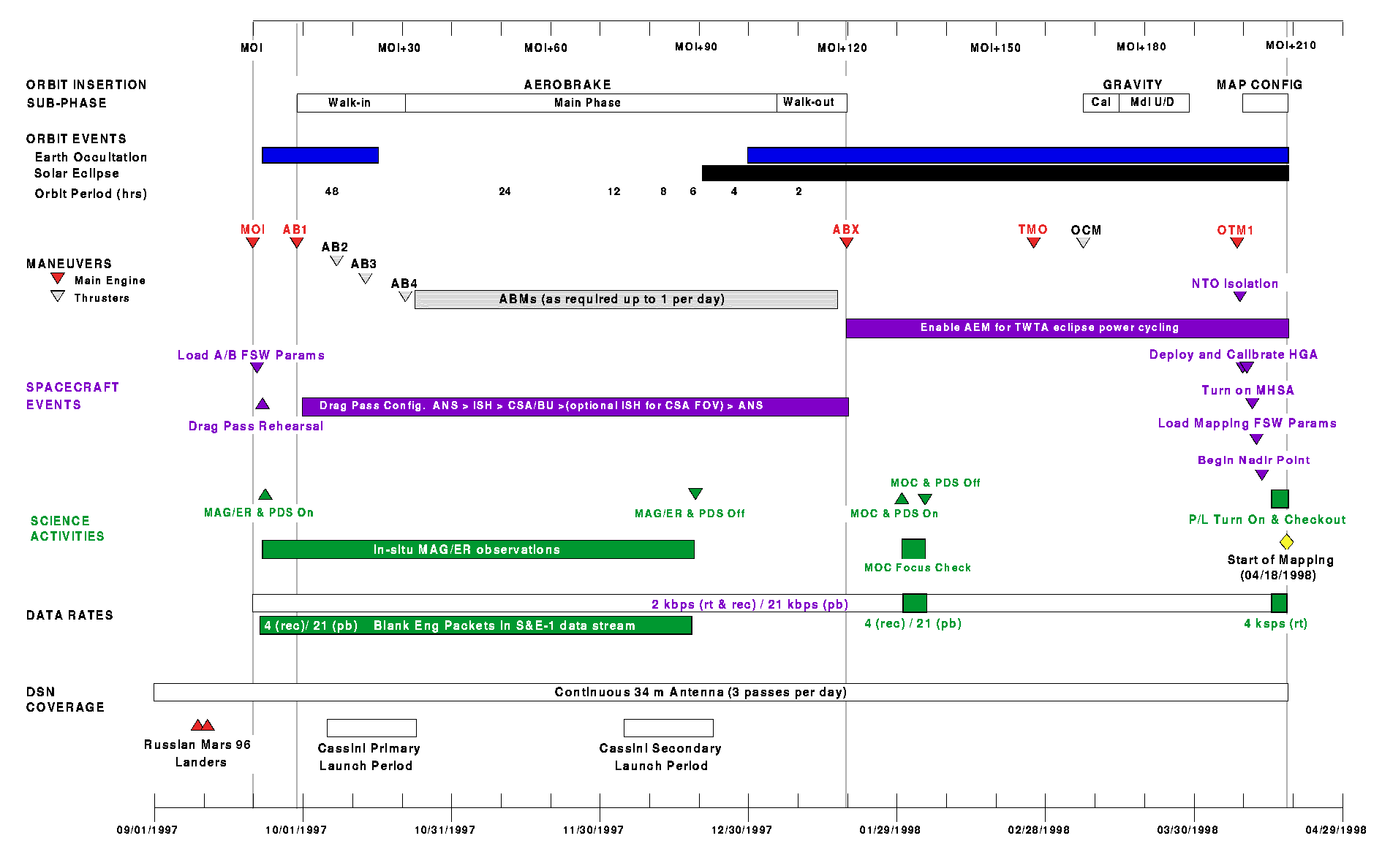
For all arrival dates, Goldstone will serve as the primary DSN site for pre-MOI coverage, while Canberra will cover post-MOI tracking. The exact time of MOI will allow approximately one hour of overlapping coverage both before and after the burn. This dual station overlap strategy will provide tracking redundancy for last minute commanding in the case of an extreme spacecraft emergency, pre-burn monitoring of spacecraft "health" and status, and post-burn acquisition of telemetry for "health" checks and navigation data. The following table lists the Mars periapsis times corresponding to specific launch and arrival dates. All times are in Ephemeris Time (ET).
Launch Date   Arrival Date  Mars             Launch Date   Arrival Date  Mars
                            Periapsis                                    Periapsis

4-Nov-96      11-Sep-97     01:27:53         15-Nov-96     15-Sep-97     01:21:07
5-Nov-96      11-Sep-97     01:27:53         16-Nov-96     16-Sep-97     01:19:29
6-Nov-96      11-Sep-97     01:27:53         17-Nov-96     16-Sep-97     01:19:29
7-Nov-96      12-Sep-97     01:26:09         18-Nov-96     17-Sep-97     01:17:52
8-Nov-96      12-Sep-97     01:26:09         19-Nov-96     18-Sep-97     01:16:14
9-Nov-96      13-Sep-97     01:24:28         20-Nov-96     18-Sep-97     01:16:14
10-Nov-96     13-Sep-97     01:24:28         21-Nov-96     19-Sep-97     01:14:40
11-Nov-96     14-Sep-97     01:22:47         22-Nov-96     20-Sep-97     01:13:05
12-Nov-96     14-Sep-97     01:22:47         23-Nov-96     20-Sep-97     01:13:05
13-Nov-96     14-Sep-97     01:22:47         24-Nov-96     21-Sep-97     01:11:32
14-Nov-96     15-Sep-97     01:21:07         25-Nov-96     22-Sep-97     01:10:01
5.1.2. Post-MOI Capture Orbit Checkout
A four and a half orbit checkout period follows MOI, to prepare for the start of aerobraking. The maneuver accuracy and resulting orbit are first determined from radiometric data and spacecraft telemetry. The health and status of the spacecraft are determined following completion of the maneuver and continually characterized in the capture orbit, specifically with respect to the new thermal environment about Mars.The first periapsis after MOI is used as an aerobraking drag pass Operations Readiness Test (ORT). The command scripts required to configure and orient the spacecraft for aerobraking, as well as various flight software parameter updates are generated and uploaded. The predicted time of periapsis is determined and the "trigger" command generated and uploaded for the on-board drag pass command script which configures and orients the spacecraft for entry into the atmosphere (described in detail in Section 5.2).
5.1.3. Spacecraft Configuration
Mars Orbit InsertionFor MOI the 590 N main engine is used to provide the required Delta-V while the 4.4 N thrusters will be used to control the spacecraft attitude during the burn. The burn sequence begins with the start of 2 kbps engineering telemetry recording on two of the recorders. The spacecraft will then turn to the pre-loaded MOI burn attitude using reaction wheel control. The TWTA beam is turned off to conserve power during the long burn and additionally because the spacecraft is occulted by Mars as viewed by Earth throughout much of the burn.
Figure 5-3: Trajectory Plot of MOI
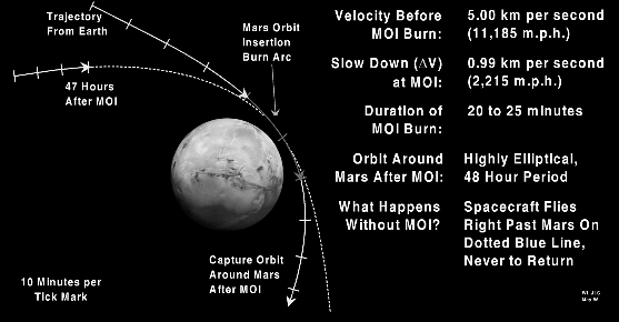
The solar arrays are then gimballed to their MOI positions, 30deg. from the +/-Y axis towards the -Z axis. This is accomplished by rotating the outboard gimbals -90deg. from their cruise configuration. Then, the catbed heaters for the 4.4 N ACS thrusters and the main engine heater are turned on at the appropriate times to ensure the optimal operating temperatures for the burn. At the required burn time, the flight software maneuver task begins firing the main engine. The burn duration varies between 20 to 25 minutes. The spacecraft executes a "pitch-over" steering strategy for MOI in order to maximize the efficiency of the burn. The attitude control thrusters are used to slew the spacecraft at a desired rate during the 20 to 25 minute burn in an attempt to keep the thrust tangent to the trajectory arc. The maneuver continues until the required DV is sensed from accelerometer data. After the burn, the spacecraft will slew back to the Earth-pointed attitude and resume the array-normal spin attitude mode. Downlink telemetry will be turned on after the burn with realtime 2 kbps engineering data. A playback of the recorded maneuver data will then follow.
The spacecraft has several levels of fault protection that can impact the success of the MOI maneuver. If position or rate thresholds are exceeded during the burn, the flight software will suspend the maneuver, swap to the alternate gyro configuration and restart the maneuver. Redundancy management software is enabled for all critical hardware components and upon detection of a fault will switch to the redundant hardware. The spacecraft also has special system level fault protection modes, designated as safe mode and contingency mode, which if entered would abort the on-board MOI sequence. These modes will be disabled at appropriate times prior to the maneuver. These times are determined by the predicted recovery times needed to reestablish the spacecraft to the required configuration for MOI.
Post-MOI Capture Orbits
With the exception of the aerobraking ORT on the first periapsis after MOI, the spacecraft remains in its normal cruise configuration throughout this period. For the aerobraking ORT, the spacecraft is commanded to its drag pass configuration and attitude as described in Section 5.2.
5.1.4. Science Activity During Mars Capture Sub-Phase
The MAG and ER are powered on throughout the Mars Capture sub-phase to take in-situ measurements. Additionally, radio science will take in-situ gravity field measurements, for which the transmitter will remain on for the entire sub-phase, with the exception of the simulated drag pass on the first periapsis after MOI. In order to collect and return the instrument telemetry, the PDS is also powered on, its RAM loaded and its data mode set for S&E-1 4 ksps recording. Normally the EDF is in mission mode when science data is collected, sending 250 bps engineering packets to the PDS to be merged with the instrument telemetry. However, due to spacecraft telemetry requirements during the orbit insertion phase, the EDF is always in engineering mode, providing 2 kbps telemetry for real-time downlink and for recording. Therefore, the PDS S&E-1 telemetry stream will have blank engineering packets in it and correlation between the instrument telemetry and spacecraft attitude is done by post-processing on the ground. Once per orbit, the recorder containing the science telemetry is played back.It is expected that two Russian Mars 96 landers will reach the Martian surface during this time. There is a Project level requirement to support the return of the lander telemetry to the Earth. However, working requirements have not currently been provided by the Russians. For now, lander support windows will be defined within which the MR and MOC will be powered on and the spacecraft slewed to point the +Z axis at nadir when within range of the lander sites. The lander data is received by the MR and inserted into the MOC data buffer. The MOC packets are then collected by the PDS and recorded onto a recorder for playback later in the orbit, when the MAG and ER data is played back.
5.2. Aerobraking Sub-Phase
5.2.1. The Basic Problem
The basic problem in designing the orbit insertion strategy is that MGS does not have enough propulsive capability to achieve the low altitude sun synchronous mapping orbit, due to the dry mass of the spacecraft (about 660 kg) and the capability of the Delta II launch vehicle (about 1060 kg to Mars). MGS will instead aerobrake from the initial 56,662 km apoapsis altitude of the Mars capture orbit down to the required 450 km altitude.Aerobraking is the utilization of atmospheric drag on the spacecraft to reduce the energy of the orbit. The friction caused by the passage of the spacecraft through the atmosphere provides a velocity change at periapsis, which results in the lowering of the apoapsis altitude. The rate at which the apoapsis altitude decreases is determined by how much drag is generated and the resulting velocity change at periapsis. Going deeper into the atmosphere will provide greater drag and reduce the orbit faster, but will consequently generate higher S/C temperatures and dynamic pressures.
One of the primary constraints driving the aerobraking timeline is illustrated in Figure 5-4 which shows the direction of approach to Mars for the interplanetary trajectory (latest launch and arrival dates) and the desired 2:00 p.m. orientation for the near-polar mapping orbit. The approach directions for the Type 2 interplanetary trajectories result in the initial orbit's dayside node being located near 5:30 p.m. if the most efficient, in-plane orbit insertion strategy were used. Rapid transition to the 2:00 p.m. orientation is beyond the spacecraft propulsive capability. This transition can be achieved much more slowly, but for no Delta-V penalty, by using the intermediate elliptical non sun-synchronous orbits during the aerobraking phase. For large elliptical drift orbits, the Sun will appear to move eastward with respect to the orbit line of nodes at a rate of about 0.5 degrees per day due to the orbital motion of Mars. The latest arrival date results in the shortest amount of time available to achieve the 2:00 p.m. orbit. Correspondingly, it represents the worst case aerobraking timeline with respect to the amount of drag and resulting dynamic pressures and temperatures on the spacecraft.
5.2.2. Aerobraking Design and Timeline
Aerobraking is comprised of three distinct phases designated as "walk-in", "main-phase" and "walk-out" (refer to Figures 5-1 and 5-2 for open and close of launch period orbit insertion timelines). Figure 5-5 is an illustration of orbit sizes at these phases. The following table summarizes the conditions at the ABX maneuver for both the close and open launch period cases for aerobraking.
Parameter                Open of Launch Period    Close of Launch Period
                         Case                     Case
Launch Date              4 November 1996          25 November 1997
Arrival Date             11 September 1996        22 September 1997
Number of Aerobrake      482                      385
Orbits
Aerobrake Completion     Jan 23, 1998             Jan 19, 1998
Date
Walk-In           Main   22 days in duration 81   22 days in duration 75
Phase                    days in duration 23      days in duration
Walk-out      Total      days in duration 126     14 days in duration
                         days in duration         111 days in duration
Mean Local Solar Time    14.06                    13.97
(hrs)
Periapsis Latitude       9deg. south              33deg. north
Apoapsis Altitude        450 km                   450 km
Periapsis Altitude       143 km                   144 km
Propulsive Delta-V                      7.58
Walk-In Main Phase       m/s              3.83    7.56 3.14  15.10
Walk-out      Total      m/s            22.60     25.80
                         m/s 34.01
Walk-In
The walk-in phase is 22 days in duration and represents the initial phase of aerobraking where the periapsis altitude is lowered in four steps (via apoapsis propulsive maneuvers) to the desired main phase altitude. The need for a gradual walk-in is due to the large uncertainty in the atmospheric density model of Mars. Additionally, the start of the aerobraking phase coincides with the start of the dust storm season. The effect of the dust storms on the atmosphere is increased atmospheric heating, which propagates to the top of the atmosphere and causes the atmospheric density to increase. How rapidly the atmospheric density changes at the main phase periapsis altitude as a result of these dust storms is not well known. Thus the time between the walk-in maneuvers allows for multiple orbits in which navigation can determine not only a measure of the atmospheric density but additionally how much it changes on an orbit to orbit basis.
Figure 5-4: Orbit Insertion Geometry
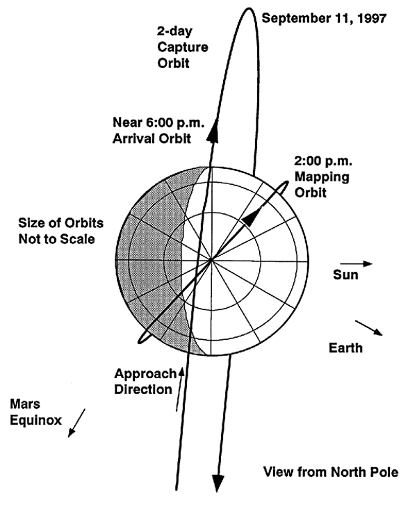
The table in sub-section 2.2.6 lists the DV allocation and resulting orbit for each of the four walk-in maneuvers. AB1 is the first walk-in maneuver and occurs 9 days after MOI, to lower periapsis altitude down to the upper fringe of the atmosphere. Additionally, AB1 is used to correct MOI delivery errors. The magnitude of this maneuver requires the use of the main engine. The actual targets for the three remaining walk-in maneuvers (AB2, AB3, and AB4) will be based on what is observed at the previous level. The step sizes for these maneuvers are much smaller and will be performed with the RCS thrusters. The number of days from the previous maneuver are eight, six, and eight, respectively for these three maneuvers.
Main Phase
The main-phase is where the majority of the orbital energy is removed and is 81 days in duration for the opening of the launch period and 75 days in duration for the latest arrival date. The main-phase is defined by the use of small propulsive maneuvers (ABMs), executed at apoapsis, to maintain periapsis within a well-defined periapsis altitude corridor, which is low enough to produce enough drag to reduce the orbit within the time constraints imposed by the 2:00 p.m. orbit, yet high enough to avoid spacecraft heating limits and maximum allowable dynamic pressure to maintain control authority over aerodynamic torques. Due to the oblateness of the Mars, the altitude of periapsis tends to rise during the main phase, so that the ABMs will be in the "down" direction to lower the periapsis altitude.
Figure 5-5: Phases of Aerobraking
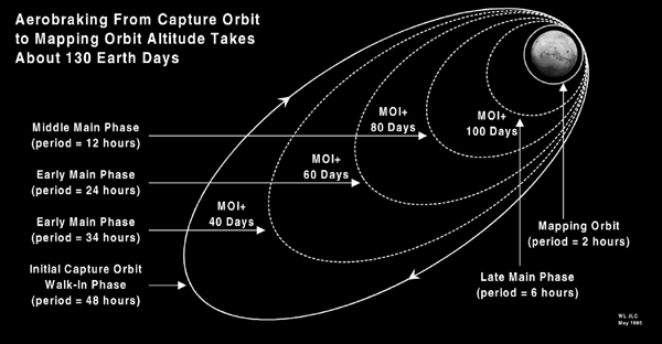
Walk-Out
The walk-out phase is 22 and 15 days, respectively, for the open and close of the launch period, and represents the final stages of aerobraking when the apoapsis altitude rapidly approaches the desired 450 km. The periapsis altitude is raised with daily ABMs, to decrease the dynamic pressure in order to maintain a 3 day orbit decay period. The 3 day orbit decay period is critical for recovery from an anomaly (e.g. contingency mode entry) which would prevent the execution of the next periapsis raise maneuver. When the desired apoapsis altitude is reached, the ABX maneuver is performed to raise periapsis to 350.8 km, ending the aerobraking phase.
Aerobraking Trajectory Design Summary and Plots
Figures 5-6 through 5-11 are plots for both the open and close of launch period cases, illustrating the key trajectory characteristics described above. A complete set of trajectory design plots for both the open and close of launch period cases are provided in the Trajectory Characteristics Document (Ref. TBD).
Figure 5-6 shows the fictitious mean Sun local solar time at the descending node. The requirement is to reach a 2:00 p.m. (14:00 hours) mapping orbit. The close trajectory follows essentially the same path as for the open, only it begins later because the arrival date is 11 days later but the node is about the same. The initial slope which continues to day 100 is due to the orbital motion of Mars around the Sun. The orbit plane moves by only a few degrees relative to inertial space during this period. The curves flatten out at 14:00 hours because the orbit becomes nearly Sun synchronous at the end of the aerobraking phase, where the apoapsis is low enough for the gravitational perturbation to precess the orbit node at the same rate as the average motion of Mars around the Sun.
Figure 5-6 (Top): Fictitious Mean Local Solar Time at the Descending Node
Figure 5-7 (Bottom): Periapsis Altitude vs. Time During Aerobraking
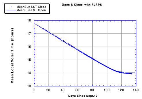
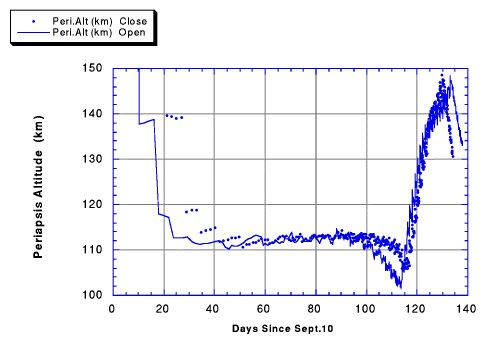
Figure 5-7 shows the periapsis altitude versus the number of days since 10 September 1997, the arrival date for the open of the launch period. The vertical axis has been limited to the period during aerobraking, following the AB1 maneuver to begin the walk-in phase. The sharp slope in the plot at the beginning of aerobraking represent the four walk-in maneuvers, as the periapsis altitude is lowered down to desired main phase altitude. The main phase begins following AB4, and the plots shows a series of ABMs are required to keep periapsis at the desired altitude. The desired altitude is determined by the aerodynamic heating rate, which depends on atmospheric density and spacecraft velocity. Although the heating rates for open and close are different, the periapsis altitudes overlap considerably during the main phase. The walkout phase begins where periodic propulsive maneuvers begin to drive the periapsis altitude higher to maintain a 3 day margin relative to the "non-recoverable" orbit. The periapsis altitude drops rapidly at the end because the last periapsis raise maneuver is one day prior to ABX (not shown).
Figure 5-8: Aerodynamic Heating Rate at Periapsis During Aerobraking
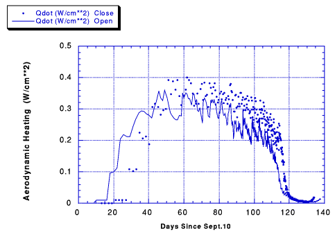
Figure 5-8 shows the aerodynamic heating rate at periapsis for the open and close trajectories. The aerodynamic heating is equal to the aerodynamic pressure times the velocity and represents the kinetic energy flux of the atmospheric molecules relative to the spacecraft. Because the planet is oblate and the equator crossing is a few minutes after periapsis during the main phase, the peak aerodynamic heating rate is as much as 1.5% greater than the value shown for periapsis at a time soon after periapsis. The aerodynamic heating rate at periapsis increases in stages during the walk-in phase. The aerodynamic heating during the main phase gradually decreases in order to counteract the growing drag duration and changing geometry relative to the Sun. The aerodynamic heating rate drops off rapidly at the start of the walkout phase, where orbit lifetime, rather than temperature drives the design.
The aerodynamic heating rate is larger for the close of the launch period because both cases follow the same local solar time plot (Figure 5.6) to reach the 2:00 p.m. orbit, but fewer days are available for aerobraking for the close case because it arrives at the planet 11 days later than the open case, but must finish aerobraking at about the same date. (Actually, the close of the launch period trajectory finishes aerobraking four days earlier than the open.) Thus, more energy must be removed each orbit in order for the close trajectory to remove the same amount of energy from the orbit in fewer days.
Figure 5-9 shows the shrinking period. The slope is slightly steeper for the close of the launch period case because greater heating rates were required to reach the 2:00 p.m. goal on essentially the same date as for the open of the launch period.
Figure 5-9: Period vs. Time During Aerobraking
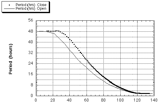
Figure 5-10 shows the argument of periapsis, measured from the ascending node in the IAU Mars equatorial system. The approximate latitude of periapsis is shown on the scale on the right. Periapsis moves slowly when the eccentricity is large, but moves more rapidly as the orbit period shrinks below five hours. On about day 120, periapsis moves by the North pole from the day side of the planet onto the night side. The arrival geometry for the close of launch period trajectory puts periapsis closer to the equator, which means that the date where periapsis is closest to the North pole is about five days later than for the open of the launch period. Since the need for the periapsis raise maneuvers to maintain a three day lifetime are loosely correlated to the point where periapsis is near the North pole, this difference effectively adds five days to the main phase for the close of the launch period, partially offsetting the later arrival which removes 11 days from the main phase. Thus the main phase heating rates associated with the close of the launch period are only slightly higher than for the open of the launch period.
Figure 5-10 (Top): Argument of Periapsis vs. Time During Aerobraking
Figure 5-11 (Bottom): Propulsive Maneuvers During Aerobraking

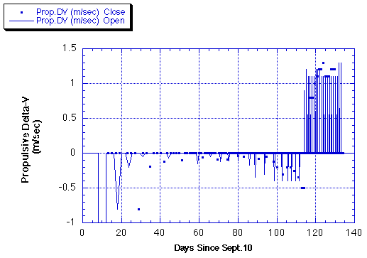
Finally, Figure 5-11 shows the propulsive maneuvers required to keep periapsis at the appropriate altitude. All of the walk-in and main-phase maneuvers lower periapsis. (During actual operations it is not inconceivable that a few maneuvers may be required to raise periapsis in response to short term variations in the atmospheric density.) When the orbit period is large, small ABMs can make a big change in periapsis altitude. This effect contributes to the larger size of the walk-out maneuvers as compared to those for walk-in. During the walkout phase, daily maneuvers are required to add one day of orbit lifetime per maneuver, resulting in a maneuver magnitude slightly more than 1 m/sec.
5.2.3. Spacecraft Configuration
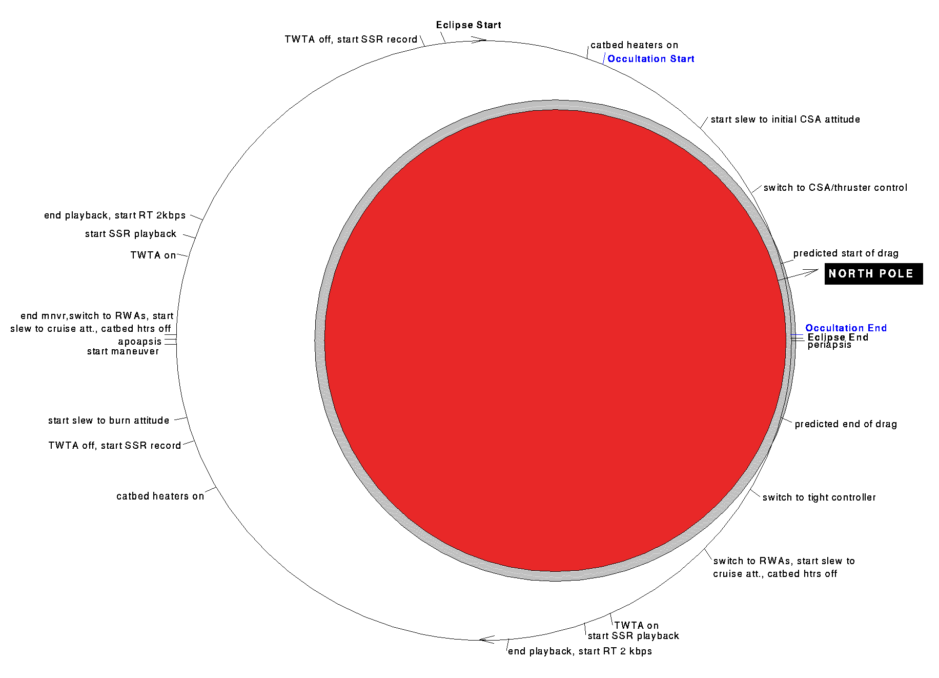
The aerobraking drag pass sequence is executed from an on-board stored sequence. The timing of events in the sequence are relative to the predicted time of periapsis passage. Timing pads are added to both sides of the periapsis passage to allow for navigation uncertainties in the periapsis crossing time. As the orbit period decreases and the drag pass durations increase, the timing between events in the sequence must be periodically updated.The aerobrake drag pass sequence begins with the catbed heaters for the thrusters being warmed up for normally 20 minutes. Engineering 2 kbps telemetry is recorded on one of the recorders. The transmitter is normally turned off to conserve power during the drag pass. The spacecraft then turns to the "tail-first" drag attitude under reaction wheel control. The desired drag entry attitude has the -Z axis aligned with the velocity vector, which keeps the science instruments and solar cells out of the incoming flow. Once the turn has been achieved, the solar arrays are then gimballed to their drag pass positions, 30deg. from the +/-Y axis towards the +Z axis. This is accomplished by rotating the inboard or elevation gimbals 90deg.. The 30deg. cant on the arrays provides for maximum aerodynamic stability, with minimal drag reduction, by moving the center-of-pressure aft of the center-of-gravity. This configuration is aerodynamically stable in that the aerodynamic torque will push the attitude back toward the aerodynamic null where the velocity lines up with the -Z axis. Additionally, this orientation puts the arrays against the hard stops to prevent back driving the gimbal motors.
At the predicted start of the pass (plus timing margin), attitude control is switched from reaction wheel to thruster control, and the wheel speeds zeroed to avoid attitude drift caused by wheel spin down. Due to navigation timing errors, thruster control is required during the drag pass as a result of the aerodynamic torques on the spacecraft being larger than the reaction wheels can counteract. In order to minimize the number of thruster firings and the amount of fuel consumed controlling the spacecraft through the drag pass, the attitude control pointing deadbands are opened up to +/-15deg.. This allows the spacecraft to oscillate around the aerodynamic null without using any propellant.
During the drag pass, steering is done using a CSA/aerobraking attitude control mode. This mode utilizes the Mars ephemeris to provide position knowledge about Mars and controls the spacecraft using the CSA and the IMU. The spacecraft -Z axis is maintained along the spacecraft velocity vector, while the +X axis is pointed in the nadir direction. Star processing is disabled during the drag pass, since the buffeting of the spacecraft by the atmosphere makes star mis-identification likely, increasing the risk of contingency mode entry. The inertial attitude reference is propagated by the gyros. At the predicted end of drag the attitude control deadbands are tightened back up to reduce the spacecraft body rates below the limits for reaction wheel control authority. After allowing for an additional delay period for timing uncertainties when coming out of the drag pass, reaction wheel control is re-enabled and the spacecraft is commanded back to the outer cruise "array-normal-spin" mode, in which the +X axis is aligned along the Earth vector, while rotating about the +X axis at 0.01 rpm. For the very small orbit periods, less than 3 hours, there is a concern that Mars may be in the field of view of the CSA upon re-acquiring the cruise attitude, extending even further the amount of time the inertial reference is not updated by star crossings. Therefore an option exists to do an set up attitude in which a desired clock angle about the X axis is acquired that will ensure the CSA is not obscured by Mars prior to commanding back to "array-normal-spin".
After commanding the turn back to "array-normal-spin", the solar arrays are subsequently repositioned back to their normal cruise configuration. The transmitter is then turned back on and a period of real-time transmission allowed for spacecraft health assessment. Following the real-time period, the engineering telemetry stored on the recorder is played back for analysis.
As described earlier, the periapsis altitude is maintained within a prescribed corridor, balancing drag levels to achieve the final orbit period against thermal and dynamic pressure constraints. The maneuvers to adjust the periapsis altitude are performed at apoapsis. It is anticipated that several maneuver sequences will be pre-loaded on-board. The maneuvers will be initiated by real-time command as dictated by ground analyses. These "pre-canned" maneuvers will have fixed delta-V amounts, but the burn directions will require periodic updating due to the location of periapsis changing throughout the aerobraking phase.
5.2.4. Science Activity
At this time, the MAG and ER are the only instruments with a requirement to collect data during aerobraking. These instruments require at least 28 days of in-situ measurements, centered around the time when the orbit period is 24 hours, to permit unique measurements of the interface between the solar wind and the Martian environment, which will not be observable from the low-altitude mapping orbit. Due to the minimal power drawn by the MAG/ER it is anticipated that they can remain on for most of aerobraking. The instrument data collection and return is identical to that described in Section 5.1.4 for the MAG/ER in the Mars Capture sub-phase.5.3. Transfer to Mapping Sub-Phase
The Transfer to Mapping sub-phase is the final period of the orbit insertion phase. Three critical events occur in this sub-phase. The first is the acquisition of the mapping orbit. Secondly a 7-sol gravity calibration is performed at the mapping orbit to update the gravity field model. Finally the spacecraft is deployed into its mapping configuration and the instruments turned on in preparation for the start of mapping.5.3.1. Mapping Orbit Acquisition
The mapping orbit for MGS is a low-altitude, near-circular, near-polar orbit which is Sun-synchronous with the dayside equatorial crossing at 2:00 p.m. mean solar time, all of which have nearly been achieved upon completion of the aerobraking phase. In order to meet altitude variation requirements in mapping for the instruments and the horizon sensor (MHSA), the mapping orbit must also be a frozen orbit with a stationary periapsis location around the South Pole. Upon completion of ABX, the periapsis latitude is 9deg.S for the open of the launch period and is 33deg.N for the close of the launch period. Propulsively moving periapsis down to the South Pole is beyond the capability of the propulsion system. The effect of the gravity field, however, is to move periapsis towards the South Pole at approximately 3.25 deg./day. Thus periapsis reaches the South Pole in 25 days for the open of launch period case. Although the trajectory has not been analyzed during this time for the close of the launch period, it is reasonable to extrapolate the data from the open launch case. Doing so indicates that approximately 40 days are required for periapsis to move over the South Pole. Once periapsis is in position, the Transfer to Mapping Orbit (TMO) maneuver is executed with the main engine to acquire the mapping orbit. The Orbit Correction Maneuver (OCM) is performed 10 days later to correct errors in the mapping orbit due to TMO execution errors and is performed with the RCS thrusters.Figure 5-12: Typical Aerobraking Orbit Profile With ABM
5.3.2. Gravity Calibration Period
After reaching the mapping orbit, a 7-sol gravity calibration period occurs (1 sol = 1 Martian solar day), during which the DSN will collect a continuous Doppler data set, except during occultations. This data set will provide the first global coverage of the gravity field at low altitude and will be used by the Navigation Team to make a first update to the gravity field model, to improve prediction and reconstruction of the spacecraft ephemeris early in the mapping phase. The mapping orbit provides a ground track pattern that nearly repeats in 88 orbits or seven Martian days (7 sols = 7.2 days), providing uniform coverage of the planet with a maximum ground track spacing at the equator of about 240 km. This provides good resolution for the gravity field solutions. The spacecraft will remain in the cruise configuration during the gravity calibration period, rotating slowly about the Earth-pointed +X axis. This configuration will minimize HGA disturbances that could degrade the Doppler measurements. After the 7-sol gravity calibration, the Navigation Team requires two weeks to update the gravity field model for mapping use. Ten days later, the first Orbit Trim Maneuver (OTM-1) is performed to freeze the mapping orbit based on the updated gravity model. As a result of the expected 3s DV magnitude for this maneuver, OTM-1 is executed with the main engine. Due to contamination of the deployed HGA during a main engine burn, the HGA cannot be deployed to its mapping position until completion of OTM-1, or in other words, once the HGA has been deployed the main engine is no longer utilized for maneuvers.5.3.3. Spacecraft and Payload Checkout Period
Upon completion of OTM-1, a period of ten days is reserved for deployment of the spacecraft into the mapping configuration and checkout of the spacecraft subsystems and instruments. This must be completed before declaring the start of the mapping phase.On the first day, the HGA will be deployed to its final mapping position as described in Section 5.3.4. The next day, an HGA calibration is performed to determine the exact position of the HGA boom and the HGA gimbal zero-reference point. On day three, the Mars Horizon Sensor Assembly (MHSA) is powered on for 48 hours prior to use in order to characterize its performance before initiating mapping control. The following day is devoted to flight software parameter uploads required to configure the spacecraft for mapping operations. Finally on day five the spacecraft is commanded to begin mapping nadir pointing. The spacecraft is monitored over the next several days to characterize its operations in the mapping configuration. Day 6 begins the payload checkout. All of the instruments and the PDS are powered on and their memory loads uplinked. Real-time data collection will take place for the next five days. During this time the routine data collection/return strategy of continuous recording at 4 ksps with daily playbacks at 21.33 ksps will be used. Upon completion of the spacecraft and payload checkout, the spacecraft will be declared ready for mapping and the mapping phase initiated.
5.3.4. Spacecraft Configuration
In the mapping orbit, the power subsystem cannot support the transmitter high power beam on during the approximately 40 minute solar eclipse period each orbit. During aerobraking, the transmitter was cycled on and off as part of the drag pass sequence of events. Upon completion of aerobraking, however, Autonomous Eclipse Management (AEM) is enabled to manage the cycling of the TWTA beam high power during the solar eclipse period of each orbit for the remainder of the mission. AEM is an autonomous eclipse detection algorithm which detects when the spacecraft enters and exits eclipse and initiates ground specified command scripts, in this case to power the transmitter off and on, respectively. Use of AEM during the transfer to mapping sub-phase allows characterization of this capability for use during mapping operations when AEM is additionally utilized to sequence the science data return events.After reaching the mapping orbit and completing the gravity calibration period, the high-gain antenna (HGA) will be fully deployed and verified. The HGA deploy sequence begins with a 20 minute warm up of the thruster catbed heaters. Next communications are switched from the HGA to the backup LGA transmit antenna (spacecraft body mounted) to ensure downlink throughout most of the deployment and in the event the boom does not deploy properly. There is insufficient link margin to transmit the telemetry over the LGA, so telemetry modulation is turned off and one of the recorders is commanded to begin recording 2,000 bps engineering telemetry for later playback. A couple of minutes prior to the deployment, the spacecraft is commanded to the "deploy/despin" attitude control mode and actuator control is switched to the thrusters. In this mode, the four reaction wheels are held in tach hold at or above 200 r.p.m. to protect them from possible shock damage when the retention and release devices are fired. The spacecraft controls to a desired attitude throughout the deployment. The HGA is deployed by simultaneously actuating three retention and release devices. The boom/antenna assembly rotates roughly 150° and latches into place within 10 minutes. Actuator control is switched back to reaction wheels and the normal cruise "array-normal-spin" mode is reacquired. The HGA is then rotated around to align the boresight back to the Earth. This is accomplished by rotating the outboard or azimuth gimbal roughly 180° followed by rotating the inboard or elevation gimbal about 30° . Upon completion of the gimbal rotation, the primary LGA (mounted to the HGA) is selected to determine if the boom deployed properly. Based on the strength of the signal a measure of any boom displacement can be determined. An HGA calibration is planned (details have yet to be determined) in order to determine the exact position of the boom. Upon determination of the actual boom position, the gimbal zero reference point is updated as required and communications reenabled over the HGA.
After verification of the HGA deployment, the IMU is commanded to the "low rate" mode to meet required mapping pointing accuracy. Additionally, the MHSA is turned on 48 hours prior to initiation of mapping nadir pointing control, in order to verify its health and characterize its operation. Various flight software parameters updates for mapping operations are subsequently uploaded to the spacecraft.
At this point the spacecraft is now ready to acquire the mapping nadir pointing attitude. In order to do this, the spacecraft is first commanded to the "inertial slew/hold" attitude control mode to slew the spacecraft such that the +Z axis is pointed at Mars. Using this mode provides autonomous payload sun avoidance protection during Mars acquisition, which is a capability not available in the mapping attitude control modes. Attitude control is then switched to "CSA/Mapping" mode to point and maintain the spacecraft +Z axis along the velocity vector. Once the MHSA has acquired "Mars Lock" in which all four quadrants are viewing Mars, attitude control is autonomously switched to "Primary" mode. In primary mode, roll and pitch control are maintained using the MHSA, while yaw is controlled using the IMU as a gyrocompass. Additionally, using the planetary ephemeris, autonomous HGA Earth tracking and solar array sun tracking are enabled. After a period of on-orbit characterization, the spacecraft is declared ready for mapping.
5.3.5. Science Activity
Apart from the payload turn on and checkout at the end of the orbit insertion phase, the only science activity is the final MOC focus check, scheduled on January 31, 1998. This focus check represents the low temperature regime in establishing the focus heater control authority.
 Return to MSSS
Home Page