Table 4: MARDI Functional Requirements/Performance
FOV                         73.4°

Exposure Time (smear        250 us (1/4 pixel @ 10 m/sec horizontal
limit)                      velocity (near-surface))

Focal ratio                 f/2

Frame Rate                  0.5 frames/sec (2 sec/frame)

Signal-to-noise             >= 20:1, for Albedo = 0.10, at aphelion,
                            with illumination angle (i) <= 75° (sun
                            elevation >= 15° )

Signal capacity             30 e- noise floor (250 usec, A = 0.10, i <=
                            75° , at aphelion) 30,000 e- full well (A
                            = 0.50, i = 0° , at perihelion)

Modulation Transfer         > 0.10 @ Nyquist
Function

Nesting Ratio               2:1 or better

Image Compression           2:1 realtime (< 2 sec) in DSP; 10:1
                            non-realtime in S/C CPU
A detailed design of the requisite lens was generated (the ray-trace
is shown in Figure 5). The lens has an effective
focal length of 7.135 mm, is f/2.0, and weighs 50 gm (of which 30 gm
is the titanium housing). There are 9 elements, including two
cemented doublets. All the surfaces are spheres except for the one
immediately after the aperture stop, which deviates less than 3 waves
at 633 nm from spherical. The optical performance properties (
Figure 6: Optical Performance of MARDI Optics
The lens barrel threads into the camera head and abuts a keyed, ground spacer ring which sets registration and focus. This makes adjusting focus and/or changing lenses (in the event of a problem) straightforward operations. The optics module is approximately 5 X 5 X 5 cm (including baffle and threads). When assembled with the other components of the camera, the optics contribute 4 cm to the overall length.
Figure 7: Block Diagram of Descent Imager Electronics
The heart of the focal plane is a Kodak KAI-1001 CCD. This detector has 1024 X 1024 9-micron pixels (1018 X 1008 photoactive), and uses interline transfer to implement electronic shuttering. The KAI-1001's fill factor of 20% causes its quantum efficiency to be low, especially red-ward of 700 nm. These effects combine to make the detector comparatively poor in sensitivity, but the optics are sufficiently fast to compensate, allowing this compact CCD to be used.
Two capabilities of the detector can be used to reduce the raw data rate from the camera. First, on-chip 2X summing can be used to add adjacent lines together in the charge domain. Second, the CCD's fast-dump feature can be used to read out only selected portions of the detector.
![]()
JPG = 58 KBytes
GIF = 165 KBytes
Figure 8: FPA (left) & DAS (right) Mechanical Prototypes and Clock
Drivers (bottom) (Boards are 5 cm by 4.6 cm)
The FPA incorporates three innovative characteristics. First, the clock drivers and their supporting voltage regulators, which ordinarily represent the largest and most complex FPA circuit block, have been implemented in an analog application-specific integrated circuit (ASIC), designed as part of the PIDDP effort and manufactured by ABB Hafo using an inherently-radhard, CMOS mixed-mode process. This device takes logic-level clock patterns from the digital electronics and converts them into the voltages appropriate for the detector. The basic ASIC is used singly or in pairs to generate the individual clock signals required by the detector (Figure 8, bottom). Detector-specific tuning is accomplished by adding a small number of discrete "select" components; for the KAI-1001 family, this tuning has already been designed and tested as part of the PIDDP development effort.
Second, a nonlinear system gain has been implemented to compress/expand the video signal strength to the counting statistics. The detector outputs an analog signal level for each pixel clocked out; this signal must be digitized for further processing and ultimately, transmission. With linear encoding, a 12-bit Analog-to-Digital Converter (ADC) would be required to capture the full dynamic range of the detector, but such devices use significantly more power than 8-bit devices. The MOC used an 8-bit ADC and programmable gain and offset modes to select the analog range to be digitized, but this resulted in both electronic and operational complexity. However, since CCDs are photon-counting devices, the statistical error for each pixel increases with the square root of the signal level, and thus, linear encoding is wasteful. As a much simpler alternative, the MARDI design uses charge-domain square root encoding. This encoding is performed by a differential MOSFET pair, encoding the full well of the KAI-1001 (~30,000 e-) into a 1-volt range, which is then digitized by a CA3318 8-bit flash ADC. This approach has the performance of 12-bit linear encoding but with lower power requirements.
Finally, a fast (30 MIPS) digital signal processor (DSP) is used to emulate the remaining video processing while embedding the CCD clock transitions directly in software. This component of the DAS (see next section) greatly reduces the complexity of the FPA.
The FPA weighs 150 gm (including 70 gm for radiation shielding), and is 4.6 X 5 X ~3 cm in size.
The DAS permits the descent camera head to act in a largely autonomous manner. To minimize the bandwidth of the CPU/DAS communications link, the DAS is capable of sustained operation with a minimum of command.
VLSI components make a highly-integrated, low-part-count digital design possible. The digital electronics use only two major components: a Digital Signal Processor (DSP) and a Field-Programmable Gate Array (FPGA).
The DSP in the DAS permits full speed software emulation of much of the usual analog processing, including correlated double sampling (CDS). Using software emulation, the zero reference ("reset") level for each pixel is digitized and stored in a register, the sum of the video plus zero reference ("video") level is then digitized, and an arithmetic subtraction is performed to produce the final result. The CCD output only requires scaling to the ADC range; no analog sampling, delay or differencing is required. In order to minimize the range of values consumed by the reset level and its noise, mean and variance statistics are accumulated along each line, line-to-line results are digitally filtered, and a control value is written to a DAC as feedback to the analog electronics.
The Motorola DSP56166 was selected because it can process 3 Mpixels/sec (30 MIPS), incorporates 2K X 16-bit data and 2K X 16-bit program memory on-chip, has two <= 15 Mb/sec serial ports that can be used simultaneously for a throughput of <= 30 Mb/sec, and its firmware can be booted over these serial lines. For the nominal frame period of 2 sec, it executes up to 40 arithmetic instructions per pixel. These performance characteristics enable this DSP to generate the CCD clocks, invert the square root transfer function implemented before quantization, perform the correlated double sampling subtraction, re-encode the video, apply lossless (2:1) first-difference Huffman compression, and transmit it digitally with handshaking over the serial communication interface to the spacecraft CPU.
The DAS also includes a field-programmable gate array (a Xilinx 3190A FPGA), used to implement high-speed logic functions such as high-speed clock patterning and interface logic; additional capacity remains for adaptation to the spacecraft interface.
The DAS mass is about 100 gm (of which 30 gm is radiation shielding). It is 4.6 X 5 X ~1.7 cm in size.
MARDI does not provide persistent storage for the DSP firmware or the FPGA configuration--when power is applied, the camera loads the DSP and FPGA code from the CPU over the serial interface (total volume of loaded code is ~12 KB). The DSP then waits for image acquisition commands over the serial input. The DSP only has 4 KB of program storage, so the software running in the DSP will be quite simple, and all DSP code will be handwritten in assembly language. Most of the DSP code will be devoted to running the camera hardware, consisting of per-frame initialization and the main loop of clock generation/pixel readout/software CDS/pixel transmission. Lossless predictive compression will also be implemented as part of the DSP firmware. The algorithm to be employed compresses each image line independently by encoding first differences with a single, fixed Huffman table. Selective readout and pixel summing can also be performed by the DSP software. The result of an imaging command will be a stream of raw or compressed 8-bit pixels.
If a timeout is detected by the CPU, it will power-cycle the system, wait for a specified period, and send the initialization sequence again.
The two Reduced Serial Interface (RSI) ports of the DSP each provide a three-signal interface (receive, transmit, and clock) at up to 15 Mbps per port. RS-422 line drivers will be used to communicate with the spacecraft through these RSI ports.
The operations part of the CPU program is relatively straightforward. Commanding code will be small (<<128 KB).
Aspects of the descent of the Mars Surveyor '98 lander create the need for both fast and slow data compression capabilities. Assuming observations during approximately 70 seconds of descent (starting about 10 seconds after parachute deployment), about ten images should be taken to provide a resolution ratio of 2:1. The PIP indicates that only 37 Mbits (roughly 4 images at 8 bits/pixel) are available for data storage. Thus, compression of somewhat over 2:1 is needed. However, while the first image has tens of seconds to be processed, the last images do not. Thus, higher compression is needed early, in order to preserve memory to hold the last images, and fast compression at the end of the descent is highly desired.
There are two ways of insuring the properly spaced (in resolution) acquisition of images. The preferred way would be to trigger each image acquisition using the descent altimeter. Thus, only those images destined to be returned to Earth would be acquired. This would also have the advantage of reducing the space needed for image storage, and hence the compression factor. For example, a 10-image sequence would require a compression factor of only 2.2:1 to meet the buffer volume limitation. Since the altitude from the radar altimeter is probably already available within the spacecraft computer (for terminal descent sequencing), either the control software could inform the camera acquisition task with, or the camera task could look at a specific location to read the present value of, the current time and altitude. This activity could run at reduced priority so as not to interfere with other, more critical functions. The acquisition software would then compare the altitude against a list of altitudes at which imaging should be performed, and trigger image acquisitions at the appropriate altitudes.
However, in order to insure that the appropriate images are acquired even if access to the altimeter is not possible, or if the software cannot provide the information in a timely manner, an alternative capability is available. If the camera acquires images continuously (e.g., once every 2 seconds), a sieving algorithm (developed during the PIDDP activity) can be used to retain select images at specified increments that will approximate the desired resolutions, even in the absence of any knowledge of altitude. The challenge is to fit these images into the available memory. All images will initially be compressed losslessly by a factor of about 2:1; this essentially doubles the available memory. As each image passes through the sieve, it is either discarded or decompressed and recompressed using the DCT compressor. The last images are stored losslessly compressed. Table 3 shows how a 10-image sequence fits within the available buffer.
MARDI has no concerns about magnetic fields, and does not generate any field.
MARDI uses no calibration targets during flight. MARDI requires a field of view of ~75° . The preferred orientation biases this FOV away from the descent propulsion system plume, towards the horizon, but includes the ground immediately beneath the spacecraft during terminal descent. For further discussion, see Section 4.3.4., below.
Under ideal circumstances, the descent imager is mounted on a small bracket on either the south or northeast footpad, and views generally downward through a cutout in the footpad approximately 3.5 cm in diameter. Figure 9 illustrates this mounting position. The electrical and data cable, connecting the camera to the spacecraft, runs through or along the leg strut, but is not structurally attached to the leg. A service loop approximately 10% longer than the maximum leg extension in included to avoid deployment mechanisms.
Figure 9: Lander Footpad Mounting Concept
The second location is on the bottom panel inboard of the northeast landing leg (between panels 1 and 2). From this location, the interface cable can be routed directly into the main spacecraft enclosure.
Footpad mounting is best for descent imaging, as it is nominally farthest from the plume of the descent propulsion system. The optical properties of the engine plumes are likely to permit imaging, although potentially degraded (hydrazine should be transparent, but thermal- and pressure-induced turbulence may produce optical distortion). The short exposure time (250 usec) mitigates some of the problems associated with the plume, but mounting the instrument as far from the effects as possible will be of great benefit.
A single port would reduce the volume and quality of the highest resolution images returned (roughly 2 fewer images, a terminal nesting scale ratio of roughly 4 rather than 2, and the two highest resolution images would have resolutions of 10 and 2.4 cm/pixel rather than 2.4 and 0.9 cm/pixel).
If possible, non-operating temperature values should be returned for health/welfare monitoring during cruise.
MARDI will need one bi-level command (Descent camera on/off).
No targets will be needed during spacecraft testing, and none will be used during flight.
The MARDI team will fully support spacecraft system-level integration and testing (I&T). The MARDI Flight Model (FM) will support flight-level testing. Details of the MARDI team support of system-level I&T will be established after selection in compliance with Mars Surveyor '98 Program requirements.
Concurrent with testing, calibration will also be performed. Calibration will measure, as a function of temperature where appropriate:
The calibration effort will rely heavily on procedures and software developed for MOC calibration.
System-level testing will use the same software framework as developed for MOC testing.
 Return to MSSS
Home Page
Return to MSSS
Home Page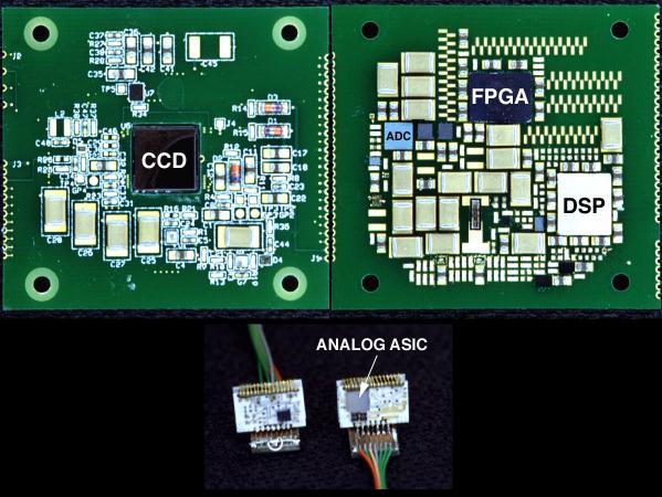