Figure 8: Block Diagram of Color Imager Electronics (per camera)
The heart of the focal plane is a Kodak KAI-1001 CCD. This detector has 1024 X 1024 9-micron pixels (1018 X 1008 photoactive), and uses interline transfer to implement electronic shuttering. The KAI-1001's fill factor of 20% causes its quantum efficiency to be low, especially red-ward of 700 nm. These effects combine to make the detector comparatively poor in sensitivity, but the optics are sufficiently fast to compensate, allowing this compact CCD to be used.
Two capabilities of the detector can be used to reduce the raw data rate from the camera. First, on-chip 2X summing can be used to add adjacent lines together in the charge domain. Second, the CCD's fast-dump feature can be used to read out only selected portions of the detector.
![]()
JPG = 58 KBytes
GIF = 165 KBytes
Figure 9: FPA (left) & DAS (right) Mechanical Prototypes
and Clock Drivers (bottom) (All to same scale, boards are roughly 5 cm
square)
The FPA incorporates three innovative characteristics. First, the clock drivers and their supporting voltage regulators, which ordinarily represent the largest and most complex FPA circuit block, have been implemented in an analog application-specific integrated circuit (ASIC), designed as part of the PIDDP effort and manufactured by ABB Hafo using an inherently-radhard, CMOS mixed-mode process. This device takes logic-level clock patterns from the digital electronics and converts them into the voltages appropriate for the detector. The basic ASIC is used singly or in pairs to generate the individual clock signals required by the detector (Figure 9, bottom). Detector-specific tuning is accomplished by adding a small number of discrete "select" components; for the KAI-1001 family, this tuning has already been designed and tested as part of the PIDDP development effort.
Second, a nonlinear system gain has been implemented to compress/expand the video signal strength to the counting statistics. The detector outputs an analog signal level for each pixel clocked out; this signal must be digitized for further processing and ultimately, transmission. With linear encoding, a 12-bit Analog-to-Digital Converter (ADC) would be required to capture the full dynamic range of the detector, but such devices use significantly more power than 8-bit devices. The MOC used an 8-bit ADC and programmable gain and offset modes to select the analog range to be digitized, but this resulted in both electronic and operational complexity. However, since CCDs are photon-counting devices, the statistical error for each pixel increases with the square root of the signal level, and thus, linear encoding is wasteful. As a much simpler alternative, the MARCI design uses charge-domain square root encoding. This encoding is performed by a differential MOSFET pair, encoding the full well of the KAI-1001 (~30,000 e-) into a 1-volt range, which is then digitized by a CA3318 8-bit flash ADC. This approach has the performance of 12-bit linear encoding but with lower power requirements.
Finally, a fast (30 MIPS) digital signal processor (DSP) is used to emulate the remaining video processing while embedding the CCD clock transitions directly in software. This component of the DAS (see next section) greatly reduces the complexity of the FPA.
The FPA weighs 150 gm (including 70 gm for radiation shielding), and is 4.6 X 5 X ~3 cm in size.
4.1.3.2. Data Acquisition System
The DAS module (Figures 7, 8 (right), and 9 (right)) extracts the analog pixel data from the FPA, digitizes it, corrects for various FPA drifts and pattern errors, and passes the resulting data to the spacecraft under CPU control. All normal pixel-related processing is performed in realtime.The DAS permits the camera head to act in a largely autonomous manner. To minimize the bandwidth of the CPU/DAS communications link, the DAS is capable of sustained operation with a minimum of command.
VLSI components make a highly-integrated, low-part-count digital design possible. The digital electronics use only two major components: a Digital Signal Processor (DSP) and a Field-Programmable Gate Array (FPGA).
The DSP in the DAS permits full speed software emulation of much of the usual analog processing, including correlated double sampling (CDS). Using software emulation, the zero reference ("reset") level for each pixel is digitized and stored in a register. The sum of the video plus zero reference ("video") level is then digitized, and an arithmetic subtraction is performed to produce the final result. The CCD output only requires scaling to the ADC range; no analog sampling, delay or differencing is required. In order to minimize the range of values consumed by the reset level and its noise, mean and variance statistics are accumulated along each line, line-to-line results are digitally filtered, and a control value is written to a digital to analog converter (DAC) as feedback to the analog electronics.
The Motorola DSP56166 was selected because it can process 3 Mpixels/sec (30 MIPS), incorporates 2K X 16-bit data and 2K X 16-bit program memory on-chip, has two <= 15 Mb/sec serial ports that can be used simultaneously for a throughput of <= 30 Mb/sec, and its firmware can be booted over these serial lines. For the nominal frame period of 2 sec, it executes up to 40 arithmetic instructions per pixel. These performance characteristics enable this DSP to generate the CCD clocks, invert the square root transfer function implemented before quantization, perform the correlated double sampling subtraction, re-encode the video, apply lossless (2:1) first-difference Huffman compression, and transmit it digitally with handshaking over the serial communication interface to the spacecraft CPU.
The DAS also includes a field-programmable gate array (a Xilinx 3190A FPGA), used to implement high-speed logic functions such as high-speed clock patterning and interface logic; additional capacity remains for adaptation to the spacecraft interface.
The DAS mass is about 100 gm (of which 30 gm is radiation shielding). It is 4.6 X 5 X ~1.7 cm in size.
4.1.3.3. Power Supply
The PIDDP breadboard uses the Interpoint MTO2815T power converter, which produces isolated +5 V and 䔳 V from a nominal 28 V input. The ripple on the 䔳 V is excessive for the front-end video circuitry, so it is downregulated with series-pass regulators (LP2951 for +12V and LM2990 for -12V) to remove ripple. The flight units will use the MRH2815T, which is a radiation-hard (105 rads Si) version in the same form-factor. Total mass, including regulators and 50 gm of radiation shielding, is under 120 grams. The dimensions of the PWR module are 5 X 3.5 X 1.3 cm.4.1.4. Software
4.1.4.1. Control Software
MARCI software runs on three processors: the main spacecraft CPU and the DAS DSPs in the two cameras. The CPU will be responsible for instrument operational commands and image post-processing and compression. The DSPs are responsible for generating the CCD clocks, emulating the required analog processing and transmitting the data output to the CPU.MARCI does not provide persistent storage for the DSP firmware or the FPGA configuration--when power is applied, each camera loads the DSP and FPGA code from the CPU over the serial interface (total volume of loaded code is ~12 KB). The DSP then waits for image acquisition commands over the serial input. Each DSP only has 4 KB of program storage, so the software running in the DSP will be quite simple, and all DSP code will be handwritten in assembly language. Most of the DSP code will be devoted to running the camera hardware, consisting of per-frame initialization and the main loop of clock generation/pixel readout/software CDS/pixel transmission. Lossless predictive compression will also be implemented as part of the DSP firmware. The algorithm to be employed compresses each image line independently by encoding first differences with a single, fixed Huffman table. Selective readout and pixel summing can also be performed by the DSP software. The result of an imaging command will be a stream of raw or compressed 8-bit pixels.
If a timeout is detected by the CPU, it will power-cycle the system, wait for a specified period, and send the initialization sequence again.
The two Reduced Serial Interface (RSI) ports of the DSP each provide a three-signal interface (receive, transmit, and clock) at up to 15 Mbps per port. RS-422 line drivers will be used to communicate with the spacecraft through these RSI ports.
The operations part of the CPU program is relatively straightforward. Commanding code will be small (< 64 KB).
4.1.4.2. Image Concatenation
WA images in each band are acquired a few lines at a time. These "strips" are too small to be independently processed, so they are combined into image buffers, one per band, until several hundred lines have been accumulated. MA images can be processed independently, owing to their larger downtrack size per band, and do not require this treatment.4.1.4.3. Data Editing/Compression
Experience has shown that the volume of data likely to be returned from a spacecraft often evolves during the development phase of a mission. Implementing data compression in software on the spacecraft computer provides the maximum flexibility for the science and spacecraft team to trade-off data return and buffer space usage. The compression modes to be provided are lossless predictive (capable of application by the DSP in realtime, i.e., < 2 sec), a relatively fast discrete cosine transform compression developed for the MOC (applied by the spacecraft CPU in "near-realtime," a few tens of sec), and high-quality lossy wavelet compression (e.g., a zerotree wavelet compressor[1], applied by the CPU on a longer timescale), each with optional pixel summing.Aspects of the Mars Surveyor '98 Orbiter data system create the need for both fast and slow data compression capabilities. A realtime, lossless compressor is needed because the instrument can acquire data at much higher rates than it can transmit them to the spacecraft over the RS-422 line. Realtime compression increases the instrument-to-spacecraft bandwidth. At low data rates, downlink bandwidth conservation is paramount, and lossy compression must be used. Here, the best quality involving loss is desired, and the wavelet compressor is used. At very high data rates, there isn't sufficient time to both fill the buffer and compress it with the wavelet compressor. The factor of four or more improvement in speed of the DCT becomes critical during these periods.
The lossless predictive compression will be implemented as part of the DSP firmware. The algorithm compresses each image line independently by encoding first differences with a single fixed Huffman table. Based on experiments performed during the design of the MOC hardware compressor, a nominal compression factor of 2:1 is expected.
The DCT compression will be a port of the MOC DCT software compressor to the spacecraft CPU. This effort should be relatively simple, since the code is already written in C. The wavelet compression will also be implemented on the spacecraft CPU. Preliminary code already exists as the result of studies to improve the MOC compression capability for MGS.
4.1.5. Fault Protection
Both the FPGA and the DSP are subject to infrequent radiation-induced upset. The DSP software will periodically check program and data memory integrity via checksums, and enter a standby state if a loss of data integrity is detected. The gate array will provide "watchdog timer" functions in case the DSP enters a program loop due to upset. If the processor fails to provide the keepalive signal, it will be interrupted and forced into the standby state. When the system enters the standby state for any reason, monitoring from the spacecraft CPU will detect this, and perform power-cycling to force reinitialization. Potentially destructive latchups of the DSP and/or FPGA (which are possible, but not expected with the selected devices) will be detected and cleared by overcurrent detection circuitry similar to that used on the MOC.4.2. System Performance
4.2.1. Resolution and Surface Coverage
The WA camera's IFOV is roughly 2.4 mrad/pixel. This translates to 0.96 km/pixel at nadir, and 4.1 km at the limb. The FOV is horizon to horizon.The MA camera's IFOV is 102 urad/pixel. This translates to 41 m at the nadir. The FOV is about 41.5 km.
4.2.2. Signal to Noise Ratios
Signal-to-noise ratios (SNRs) have been computed for low albedo (0.1), solar incidence angle of 70°, and illumination conditions at aphelion (Table 5). These values are considerably worse than what will be encountered, but are representative of, for example, polar conditions. SNRs at brightest illumination conditions (solar incidence of 0° at perihelion) are 4.28X higher. In the case of the RED and BLU filters of the WA camera, this will exceed the full well capacity of the CCD, and shorter exposures will be used.Table 5: MARCI SNRs
	   WA SNR                    MA SNR
	Filter    SNR           Filter     SNR
	 UV1       32(1)            425      300
	 UV2       28(2)            500      400
	 BLU      341              550      420
	 RED      494              650      290
	 NIR      108              750      120
	             	           860       48
        	 	           900       35
                	           930       27
                        	   950       22
	                           975       18
         (1) 8 x 8 summing
         (2) 2 x 2 summing
4.2.3. Data Rates and Volumes
The raw data rate from the WA is 29.6 Kbps per band (148 Kbps for 5 bands). The raw rate from the MA is 704 Kbps per band (7.04 Mbps for 10 bands).There are two factors limiting the volume and rate of data return: the rate allowed by the communications port with the spacecraft, and the downlink data rate/volume. The intrinsic data rate of the WA camera is sufficiently low that all five bands could be acquired simultaneously at full resolution. However, at the lowest downlink rate, only 21.5 Mbits of camera data may be downlinked per day. Pixel summing can be used to reduce the raw data by an amount that scales as the square of the pixel summing factor. A single band global color map at 8X reduced resolution (7.2 km/pixel) requires 22.5 Mbits/band uncompressed. Therefore, a factor of 5 lossy compression must be employed to acquire 7.2 km/pixel global maps in all five bands.
The MA camera intrinsic rate exceeds the 1 Mbps rate accommodated by the RS-422 line for all but a single-channel acquisition. Realtime 2:1 lossless compression and/or pixel summing is used to acquire multiple channels. However, as seen in Table 6, there are excellent acquisition scenarios even under these limitations. As will be noted in Section 4.4.5. Telemetry, MARCI can greatly benefit from having access a second RS-422 channel, should this port exist on the Orbiter, as it would permit both additional bands and data with greater spatial resolution to be acquired.
Table 6: Data Rate Use by Medium and Wide Angle Cameras
      Medium Angle Camera                 Wide Angle Camera         Rate, Mbps

10 bands, 3 X 3 summing (120 m/pxl)    5 bands @ full resolution       0.93

5 bands, 2 X 2 summing (80 m/pxl)      4 bands @ full resolution       1.0

1 band, full resolution                5 bands @ full resolution       0.85
4.3. Advanced Technology
As previously described, MARCI incorporates "state-of-the-art" imaging technologies without requiring new developments. The advanced technologies it uses have been validated by the PIDDP effort. Among the new technologies used are: flip-chip surface mounting of components using conductive adhesives (conductive surface mount adhesives, or CSMA), analog application specific integrated circuits, signal companding in the analog domain using a differential MOSFET pair, use of a megapixel electronically-shuttered CCD detector, Correlated Double Sampling in the digital domain using a digital signal processor, and clock signal patterning using an FPGA. Use of these technologies results in a highly capable, very low-mass instrument that is reliable (through the use of small numbers of standard components), reprogrammable (through extensive use of firmware and FPGA "logicware" to replace hardware), and easily manufactured (due to low part count and advanced fabrication techniques). These technologies are enabling, allowing imaging instruments to be used in circumstances traditionally thought too constrained for them.4.4. Payload/Instrument Integration Requirements
4.4.1. General
The only radiation sensitive part in the design is the CCD, which will require spot shielding to < 2-4 Krad. Other portions of the electronics are radiation tolerant, but possibly prone to single event upsets or latchups (SEU or SEL). As described in Section 4.1.5, latchup detection and reset circuitry will be used to protect against SEL, and software will be used to mitigate SEU.MARCI has no concerns about magnetic fields, and does not generate any field. It requires no space-deployable covers (a "remove before launch" cover will be used to maintain cleanliness during ATLO), and uses no calibration targets during flight. No spacecraft maneuvers are required during mapping--the normal spacecraft motion provides the appropriate acquisition geometry.
4.4.2. Power
Each camera uses ۯV and 䔰V regulated power, provided by its own power supply, and draws 2 W operating, 0.1 W standby from the spacecraft unregulated 28 V power supply. The cameras may be operated separately or together. Additional power will be used on occasion and when available for data compression, which will vary with data rate.4.4.3. Thermal
The MARCI operating temperature range is -40° to +70° C. Survival temperature range is -80° to +100° C. Multilayer insulation (MLI) and replacement heaters will be used to maintain survival temperature during the cruise and orbit insertion (aerobraking) mission phases. Once operational, the cameras do not need replacement heat unless powered-off (the standby power can maintain their temperature for short periods of time during sequencing).4.4.4. Mechanical
The two MARCI cameras easily fit within the volume and areal constraints noted in the PIP. However, a FOV conflict is apparent, as shown in Figure 10. The solar panel rotates through the WA FOV as the spacecraft passes over the north pole and moves southward. The field of obscuration begins near the center of the westward portion of the FOV, moves to obscure from that point to the western limb, and then exits the FOV at that limb. Owing to the close proximity of the panel to the camera, the amount of obscuration is quite large.
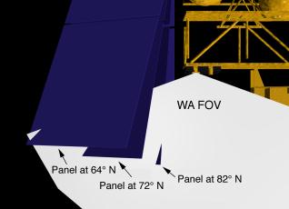
Figure 10: Obscuration of WA FOV by Solar Panel in Northern
Hemisphere
Mars Observer encountered a similar problem during the early design phases of the mission (January through May 1987). The problem was eventually solved by moving the camera and the solar panel attachment point. Recognizing the cost and time constraints under which Mars Surveyor '98 Project is laboring, this conflict may not be solvable. However, the scientific advantages of seeing both limbs is quite high, and some discussion of the problem would seem prudent.
It is not possible to determine if there is a FOV conflict with PMIRR from the available drawings. If there is, it is not serious and can be accommodated by moving the camera in the +X direction or raising it slightly in the +Z direction.
Lack of resolution of the solar array FOV obscuration would not preclude accomplishing most of the science objectives of this experiment. The investigation is prepared to work with the Project and spacecraft manufacturer to insure the maximum science return within the constraints under which the Project must operate. In any case, it is extremely important to reach agreement on FOVs and other aspects of the physical interfaces early in the interface discussions.
4.4.5. Telemetry
The orbiter cameras require as high a data rate to the spacecraft as can be accommodated. The spacecraft description in the PIP indicates that at least one RS-422 port, capable of supporting 1 Mbps, is available to the payload. Since PMIRR has been selected for the Mars Surveyor '98 mission and has a data rate (150 bps) that can be accommodated on one of the lower rate channels, this proposal assumes that MARCI will have access to the 1 Mbps channel.Each camera's DSP provides two Reduced Serial Interface ports that can be run with external clock lines and 8- or 16-bit framing at data rates of up to 15 Mbits/sec per port. Port 0 on each will be directly connected (through RS-422 line drivers) to the spacecraft communications port through cross-strapping. The DSPs will be interconnected on their second ports (see Figure 11). In this configuration, either camera can be powered and operated with the other turned off. For simultaneous operation, the MA DSP will put its port 0 in a high-impedance state, and transmit its data to the WA DSP via port 1; the WA DSP will relay MA data to the spacecraft at idle times. This arrangement provides redundancy, since should one camera fail, the other can still be operated without any degradation.
Figure 11: Diagram of Cross-strapping of Data Ports of the
MARCI cameras.
If a second RS-422 port is available (as it is on the Mars Surveyor '98 Lander), somewhat different cross-strapping would be used to insure proper communications. However, there are distinct advantages to having a second port, as it doubles the data rate from the instrument to the spacecraft, which is highly desired but not essential to the experiment (See also Section 4.2.3. Data Rates and Volumes).
If possible, non-operating temperature values should be returned for both cameras (focal planes) for health/welfare monitoring during cruise.
4.4.6. Command
MARCI requires a relatively small number of uplink commands. The orbit-to-orbit imaging sequence is determined on the ground. This sequencing is performed entirely within the investigation team--outside support is limited to navigation predictions and uplink telecommunications. Approximately 4 Kbytes (34 Kb) of uplink are needed during high downlink data rate periods, and proportionally lower uplink volume is needed during lower downlink periods. These uplink values are entirely memory uploads, and do not involve spacecraft-interactive commanding.MARCI will need four bi-level commands (WA camera on/off, WA Survival Heater on/off, MA camera on/off, MA Survival Heater on/off).
4.4.7. Attitude
MARCI places no constraints on the orientation of the orbiter, nor on the ability to control that orientation, other than as noted in the PIP. The FOVs of both cameras have been sized to accommodate the 25 mrad control capability about the X-axis, and operation as framing cameras provide post-receipt reconstructive capability for motion about the Y- and Z-axes. Both stability and post-reconstruction knowledge is acceptable.4.4.8. Integration and Ground Operations/ Testing
MARCI should be relatively simple to integrate with the spacecraft, provided interfaces are established early. Interface connections consist of two 28 V power and one three-signal data interfaces.An aliveness target will be needed during spacecraft testing, but no targets will be used during flight.
The MARCI team will support spacecraft system-level I&T through a combination of remote and local participation. The MARCI Flight Model (FM) will support flight-level testing. Details of the MARCI team support of system-level Integration and testing (I&T) will be established after selection in compliance with Mars Surveyor '98 Program requirements.
4.5. Test and Calibration
4.5.1 Instrument-level
Tests will be performed to verify correct functioning of the instrument. These tests will include board-level verification of each major subsystem, system-level tests after board integration, and environmental testing (thermal/vacuum and vibration.) The Ground Support Equipment and breadboard developed for PIDDP will be used to support standalone operation.Concurrent with testing, calibration will also be performed. Calibration will measure, as a function of temperature where appropriate:
- absolute photometric performance
- system noise performance
- optical distortions (geometric and photometric)
- system Modulation Transfer Function over field
- stray light susceptibility
The calibration effort will rely heavily on procedures and software developed for Mars Observer and Mars Global Surveyor Orbiter Camera calibration.
4.5.2. System-level ATLO
After integrating with the spacecraft, the MARCI team will verify continuing correct operation by developing Initial Power Turn-On (IPTO) and Functional Electrical Test (FET) procedures. These tests can be executed at various times during spacecraft testing to confirm that the instrument is still functioning properly; they can also be used to investigate possible interactions, such as EMI, between MARCI and other spacecraft systems. No calibration targets or other support hardware are required.System-level testing will use the same software framework as developed for MGS MOC testing.
4.6. Ground and Flight Operations
As in the system developed for MOC, a high degree of automation is used to minimize costs and maximize efficiency of work flow. The system will rely on significant heritage with the MOC system both because of its robust and mature state and to minimize development costs.As is the case for the MOC, the WA camera will always be operating in a low-resolution mapping mode. At low data rates, returning the data from even this low resolution mode is difficult, and additional compression is required. During periods of higher downlink bandwidth, however, not only can the WA data be acquired at higher resolution and/or without compression, but selected areas can be imaged using the MA camera. Thus, bandwidth resource allocation within the instrument (i.e., transparent to the spacecraft) is needed. The problem of allocating resources between different imaging possibilities is well understood from work on the MOC; straightforward modifications to the MOC uplink planning tools can accommodate MARCI planning as well.
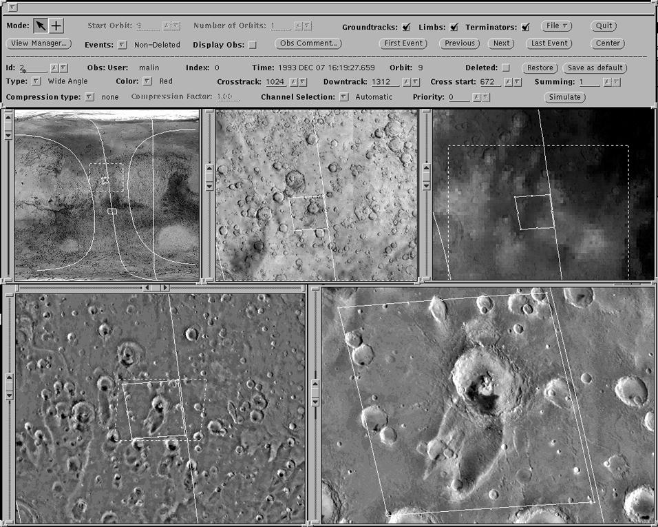
For the MOC, uplink planning follows two paths: time-independent opportunities can be identified at any time, and entered into the observational target list. They are automatically and continually compared with orbit predict data for the next operational period and, if viewable, the observations are tagged for acquisition. Conflicts are resolved automatically by use of a priority scheme. Time-dependent observations are those that are time-critical, or that come up as targets of opportunity. These are combined with the scheduled observations manually; conflicts are resolved by changing image parameters (such as size, or compression factor) and resimulating the instrument performance of the sequence at many times the "real" sequence execution rate. The basic software to perform both of these planning tasks already exists (e.g., Figure 12).
![]()
JPG = 166 KBytes
GIF = 632 KBytes
Figure 12: Screen view of MOC Time-Dependent Targeting Tool, showing
Mars Digital Image Mosaic as base for targeting, with orbit information
(location, limb, terminator, etc.) and image acquisition parameters (image
size, sampling, compression, etc.)
Software also exists to convert sequences to instrument commands, and to convert instrument commands into formats suitable and acceptable for uplinking through JPL to the spacecraft. The MGS concept of "Express Commanding" was developed in response to the MOC commanding philosophy, and is credited with the potential of greatly reducing mission operations costs.
To MARCI Table of Contents
To Previous Section
To Top of This Section
To Next Section
Return to Mars Page
 Return to MSSS
Home Page
Return to MSSS
Home Page
Return to MSSS
Home Page